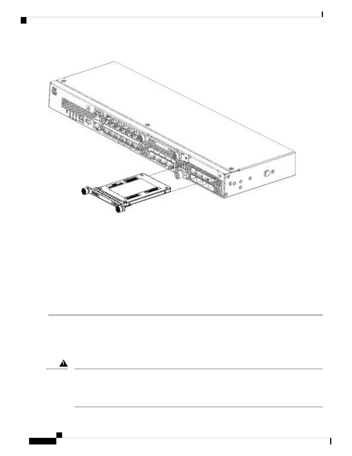
Figure 47: Remove the SSD
Step 4 To replace the SSD in slot 1, make sure the power switch is still in the OFF position, and then hold the SSD in front of
slot 1 and push it in gently until it is seated.
Step 5 To install the MSP SSD, make sure the power switch is still in the OFF position, and then remove the blank faceplate in
Slot 2 by loosening the captive screws on either side of the faceplate.
Step 6 Hold the MSP SSD in front of slot 2 and push it in gently until it is seated.
Do not switch the two SSDs. The MSP MUST be installed in slot 2. If you remove it and install it in slot 1, all
stored file capture data are lost.
Caution
Step 7 Tighten the captive screws on either side of the SSD.
Step 8 Check the SSD LED to make sure the SSD is operative. See Front Panel LEDs, on page 10 for a description of the SSD
LEDs.
Remove and Replace the Power Supply Module
Take note of the following warnings:
Statement 1002—DC Power Supply
When stranded wiring is required, use approved wiring terminations, such as closed-loop or spade-type with
upturned lugs. These terminations should be the appropriate size for the wires and should clamp both the
insulation and conductor.
Warning
Cisco Firepower 2100 Series Hardware Installation Guide
70
Maintenance and Upgrade
Remove and Replace the Power Supply Module
 Loading...


