Network activity
• Off—No connection or port is not in use.
• Amber—No link or network failure.
• Green—Link up.
• Green, flashing—Network activity.
7
Rear Panel
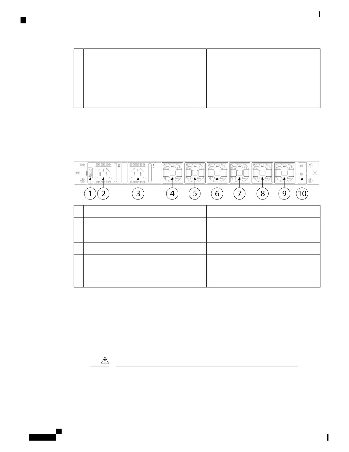
The following figure shows the rear panel of the Firepower 4100.
Figure 7: Firepower 4100 Rear Panel
Power supply module 12Power on/off switch1
Fan module 14Power supply module 23
Fan module 36Fan module 25
Fan module 58Fan module 47
Location for the two-post grounding lug
The two-post grounding lug is
included in the accessory kit.
Note
10Fan module 69
The power switch is located to the left of power supply module 1 on the rear of the chassis. It is a toggle
switch that controls power to the system. If the power switch is in standby position, only the 3.3-V standby
power is enabled from the power supply module and the 12-V main power is OFF. When the switch is in the
ON position, the 12-V main power is turned on and the system boots.
You can shut down the chassis in one of two ways:
• Perform a graceful shutdown using the shutdown commands (see the FXOS CLI Configuration Guide
for the procedure). This may take several minutes to complete. Then toggle the power switch to the OFF
position. The power LED changes from solid green to off immediately.
If you move the power switch to the OFF position before the shutdown command
sequence is complete or if you remove the system power cords before the graceful
shutdown is complete, disk corruption can occur.
Caution
Cisco Firepower 4110, 4120, 4140, and 4150 Hardware Installation Guide
10
Overview
Rear Panel
 Loading...


