To remove a QSFP+ or QSFP28 transceiver module, follow these steps:
Step 1
For optical QSFP+ or QSFP28 transceiver modules, disconnect the network interface cable from the QSFP+ or QSFP28
transceiver connector.
Step 2
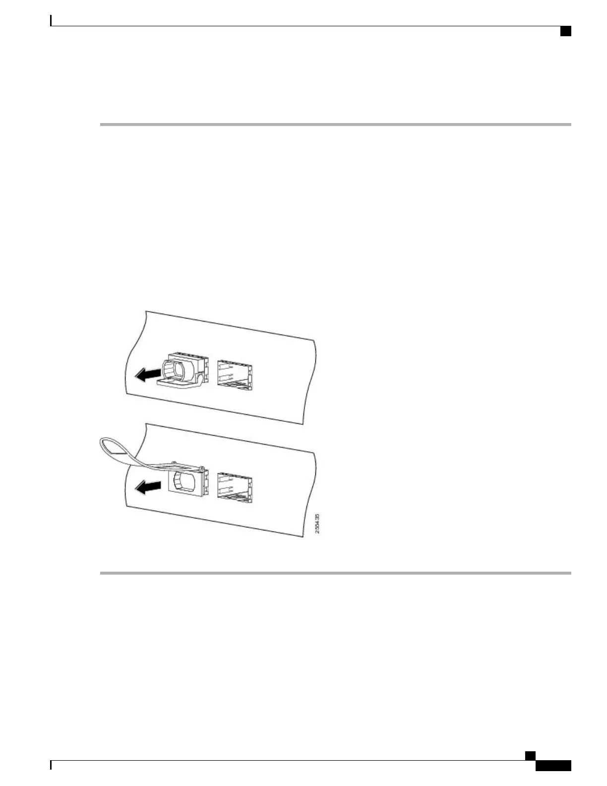
For QSFP+ or QSFP28 transceiver modules equipped with a bail-clasp latch (see the below figure, top view):
a) Pivot the bail-clasp down to the horizontal position.
b) Immediately install the dust plug into the transceivers optical bore.
c) Grasp the sides of the QSFP+ or QSFP28 transceiver and slide it out of the module socket.
Step 3
For QSFP+ or QSFP28 transceivers equipped with a pull tab latch (see the below figure, bottom view):
a)
Immediately install the dust plug into the transceiver’s optical bore.
b) Grasp the tab and gently pull to release the transceiver from the socket.
c) Slide the transceiver out of the socket.
Figure 30: Removing the 40-Gigabit QSFP+ or 100-Gigabit QSFP28 Transceiver Module
Step 4
Place the QSFP+ or QSFP28 transceiver module into an antistatic bag.
Connecting Interface Ports
You can connect optical interface ports on line cards with other devices for network connectivity.
Hardware Installation Guide for Cisco NCS 5500 Series Fixed-Port Routers
49
Connect Router to the Network
Connecting Interface Ports
 Loading...