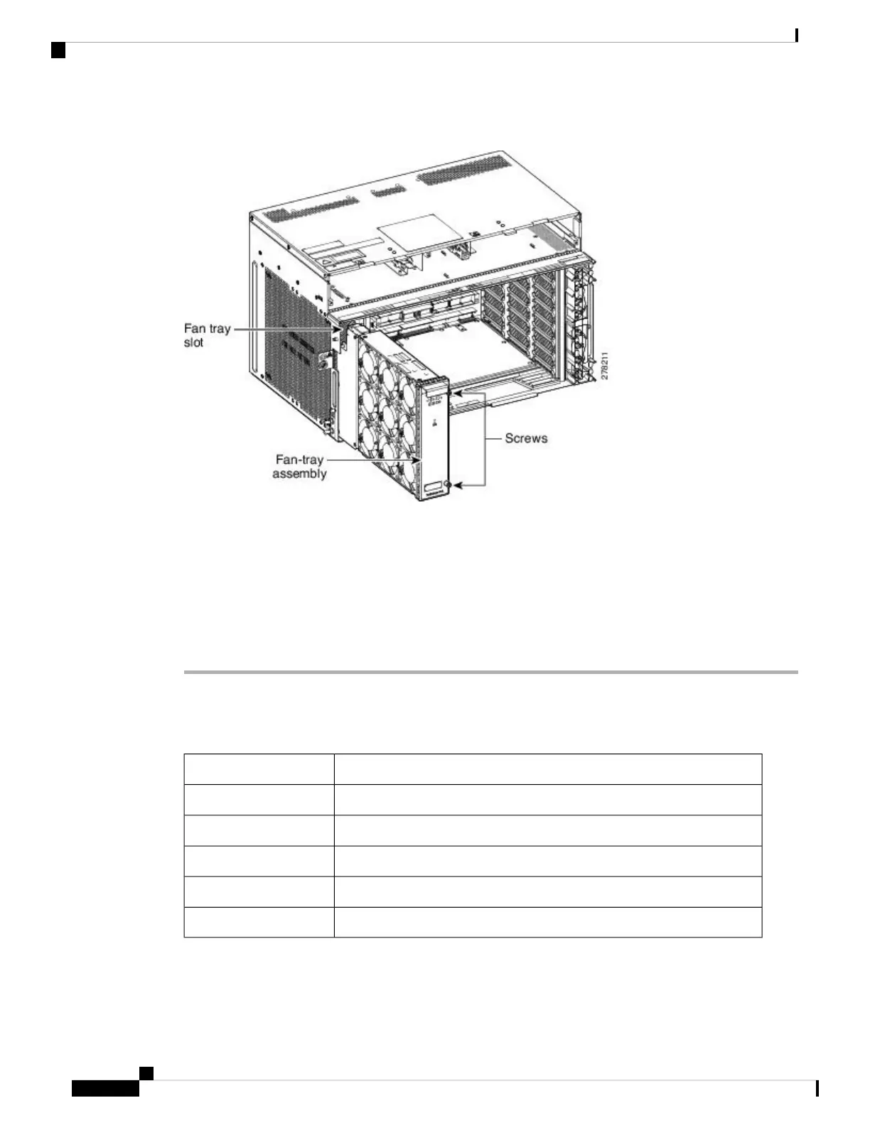
Figure 19: Fan-Tray Extracted
Step 6 Slide the new fan-tray into the shelf assembly until the electrical plug at the rear of the tray plugs into the
corresponding receptacle on the backplane.
Step 7 To verify that the tray has plugged into the backplane, ensure that the LED on the front of the fan-tray is
activated.
If you removed the door, complete the NTP-G258 Install the Standard Door of the ONS 15454 M6 Shelf .
Stop. You have completed this procedure.
NTP-G117 Replace the ANSI Shelf Alarm Interface Panel
This procedure replaces the AIP on the ONS 15454 ANSI shelf assembly.Purpose
#2 Phillips screwdriverTools/Equipment
NonePrerequisite Procedures
As neededRequired/As Needed
Onsite or remoteOnsite/Remote
Provisioning or higherSecurity Level
Maintaining the ONS 15454 M12 (ANSI and ETSI), ONS 15454 M2 and ONS 15454 M6 Shelf
26
Maintaining the ONS 15454 M12 (ANSI and ETSI), ONS 15454 M2 and ONS 15454 M6 Shelf
NTP-G117 Replace the ANSI Shelf Alarm Interface Panel

 Loading...