17
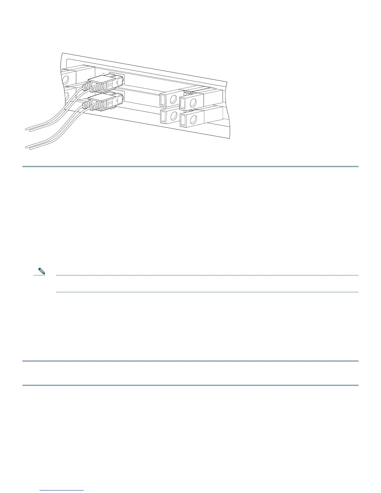
Figure 10 Cabling the 10 GBE Interface
The Link LED should be green.
6 Completing the Installation
This module explains how to verify link connectivity and how to install a Cisco service control application.
Examining the LEDs
• The 10 GBE Link LED should be green. This indicates that an active connection exists.
• The 10 GBE RX and TX LEDs (if flashing green) indicate that traffic is being received or transmitted by the SCE 8000
platform, respectively.
Note In an inline topology, the RX and TX LEDs indicate that packets are being received and transmitted by the
SCE 8000 platform.
• In optical splitter topologies, the RX LEDs are the sole indicators. The TX LEDs do not blink, because the TX is not
connected to the port in this topology.
Performing Final Installation Verification
Viewing 10-Gigabit Ethernet Port Status
Step 1 At the Cisco SCE> prompt, type show interface TenGigabitEthernet 3/ baynumber /0.
This displays the port link status.
The following example shows how to display a system response.
Cisco SCE8000>show interface TenGigabitEthernet 3/1/0
Actual Status:
Link is on
Bandwidth: 10000000Kbps
Burst-size: 500000bytes
270979
SCE8000-SIP
STA
TU
S
AC
T
IV
E/L
IN
K
SPA-1X
1
0GE-L-V2
S
TA
TU
S
A
C
T
IV
E/
L
IN
K
SPA-1X
1
0GE-L-V2

 Loading...


