7
Before you connect system power or turn on the Cisco SCE 8000 chassis, you must complete this procedure:
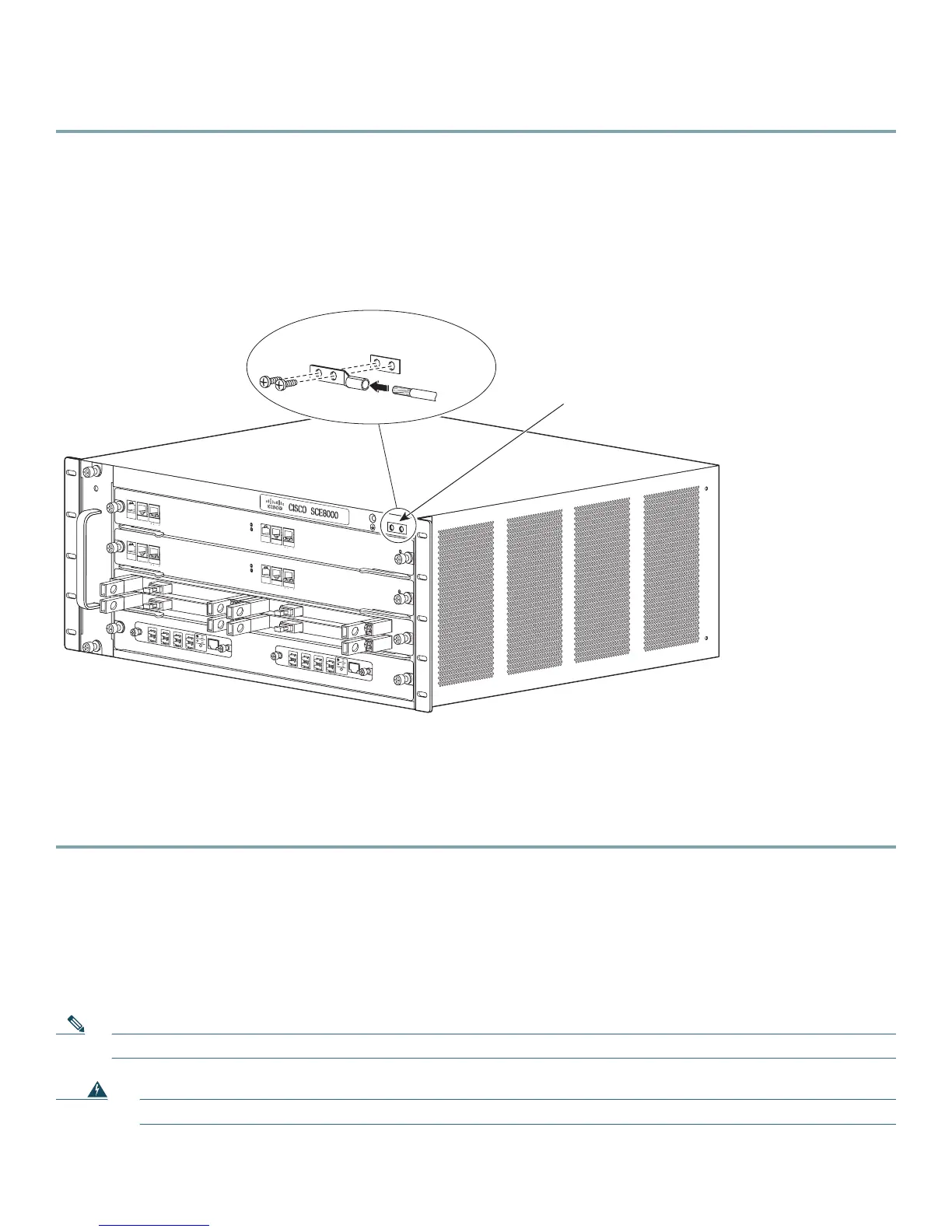
Step 1 Remove approximately 0.75 inch (19 mm) of the covering from the end of the grounding wire using a wire-stripping
tool.
Step 2 Insert the stripped end of the grounding wire into the open end of the grounding lug.
Step 3 To secure the grounding wire in place in the grounding lug, use the manufacturer recommended crimping tool.
Step 4 Locate and remove the adhesive label from the system grounding pad on the chassis (Figure 4).
Figure 4 Installing the System Ground
Step 5 Place the grounding wire lug against the grounding pad, making sure that solid metal-to-metal contact exists.
Step 6 Secure the grounding lug to the chassis using two M4 screws. Ensure that the grounding lug does not interfere with
other hardware or rack equipment.
Step 7 To ensure adequate earth ground for the Cisco SCE8000 chassis, prepare the other end of the grounding wire, and
connect it to an appropriate grounding point at your site.
Connecting Power
The following sections describe how to reconnect the AC or DC power.
Installing a DC-Input Power Supply
Note The DC return must remain isolated from the system frame and chassis (DC-I).
Warning
Before you perform any of the following procedures, ensure that power is removed from the DC circuit.
F
AN
STAT
U
S
SCM
1
SCM
2
S
I
P
3
4
S
CE
8
00
0
-FA
N
S
YS
TE
M PO
W
E
R
OPT
I
C
AL
BY
P
A
S
S
S
T
A
T
US
A
U
X
P
O
R
T
2
L
INK
A
C
T
I
V
E
MA
STER
SC
E8
0
0
0
E
X
T
E
N
DE
D SERVI
C
E
CO
N
T
ROL
M
O
D
U
L
E
O
PTI
C
AL
B
YP
A
S
S
OP
T
IC
A
L
B
YP
AS
S
C
O
NSO
L
E
1
0
10
0
1
0
0
0
L
INK
A
CTI
V
E
P
O
R
T1
A
C
A
B
C
D
B
D
S
TA
TUS
C
TR
L
O
PB
-
SC
E8
K
-
MM
OP
T
I
C
AL
B
YP
A
S
S
1
TX
R
X
TX
RX
TX
RX
TX
R
X
A
C
A
B
C
D
B
D
S
T
A
T
U
S
C
T
RL
O
PB-SC
E8
K
-M
M
O
PT
ICA
L
BY
P
A
SS
2
T
X
R
X
T
X
R
X
T
X
R
X
T
X
R
X
S
Y
ST
EM
P
O
W
ER
OP
T
I
C
AL
BY
P
A
S
S
ST
A
T
U
S
A
UX
PO
R
T2
1
0
10
0
1
0
0
0
L
I
N
K
A
C
T
I
V
E
M
AS
T
ER
SC
E8
0
0
0
E
X
T
E
N
DE
D
SERVI
C
E
CO
NTROL
M
O
D
U
L
E
S
C
E
8
00
0
-
SC
M
-
E
S
C
E
8
00
0-
SC
M
-
E
S
C
E
8
0
00-
S
I
P
C
O
NSO
L
E
1
0
10
0
1
0
0
0
L
INK
A
CTI
V
E
P
O
RT 1
O
P
T
I
C
A
L
B
YP
A
SS
OP
TIC
A
L
B
YPA
S
S
ST
A
T
U
S
A
CT
I
V
E
/
L
I
N
K
SP
A-1X
1
0
G
E
-L
-V
2
ST
A
T
U
S
A
C
T
I
V
E
/
L
I
N
K
SP
A
-1
X
1
0
G
E-L
-V
2
S
T
A
T
US
A
CT
I
V
E
/
L
I
N
K
S
P
A-1
X
1
0
G
E-L
-
V
2
ST
A
T
U
S
A
C
T
I
V
E
/
L
I
N
K
S
P
A-1
X
1
0
G
E-L
-V
2
1
0
1
0
0
1
0
00
270892
System ground
connector
System ground
connector
Grounding
lug
Wire

 Loading...


