6
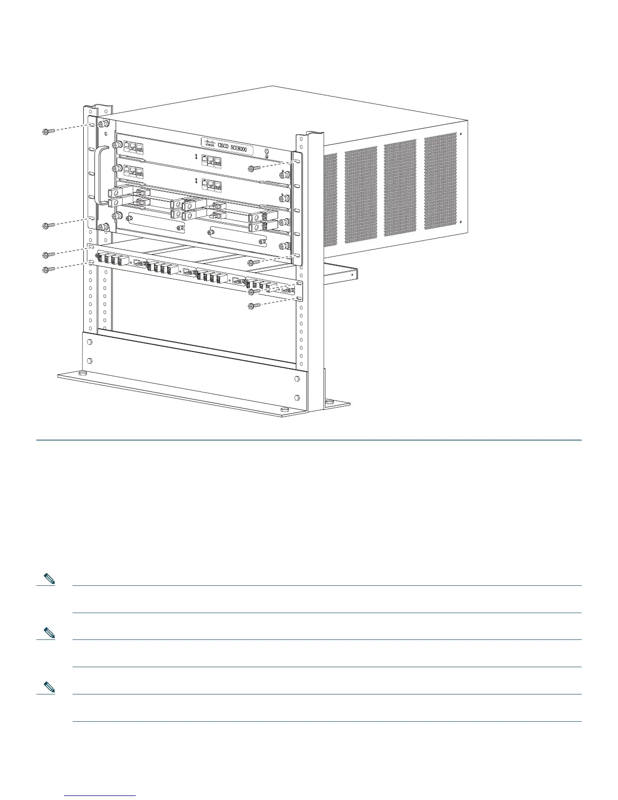
Figure 3 Optical Bypass Modules in External Mounting Panel
3 Connecting Power Supply Units
The SCE8000 chassis is shipped with the power supplies (AC or DC) already installed. This section provides information for
grounding the SCE8000 platform and connecting the AC or DC power supply units.
Connecting the Chassis Ground
Note If this equipment is installed in a U.S. or European Central Office, you must connect the system ground on both AC
and DC-powered systems to an earth ground.
Note For DC-powered systems, the system ground is also the power supply ground. The DC ground must be installed with
a permanent connection to an earth ground according to NEC guidelines.
Note When you use the PWR-2700-DC/4 power supply in the Cisco SCE8000 chassis, additional grounding requirements
exist.
Two threaded M4 holes are provided on the chassis frame to attach the ground cable.
270994
FA
N
S
T
AT
U
S
SC
M
1
SC
M
2
S
IP
3
4
SCE80
00-F
AN
SY
S
T
E
M
PO
W
E
R
OP
TI
C
A
L
B
YPA
S
S
S
TATU
S
A
UX
P
O
R
T
2
L
IN
K
A
C
TI
VE
MA
STE
R
S
C
E
8
0
0
0
E
X
T
E
N
D
E
D
S
E
R
V
I
C
E
C
O
N
T
R
O
L
M
O
D
U
L
E
OP
T
ICAL
BYPASS
O
PT
I
C
A
L
BYPASS
CO
N
SOLE
1
0
1
00
1
0
00
L
I
N
K
AC
TI
VE
PORT
1
S
Y
S
T
E
M
P
O
W
ER
OP
TI
C
A
L
B
Y
P
A
S
S
S
TATU
S
A
U
X
POR
T
2
10
10
0
10
0
0
L
I
N
K
A
C
T
I
V
E
M
A
S
TE
R
S
C
E
8
0
0
0
E
X
T
E
N
DE
D
S
ER
V
I
C
E
C
ON
T
R
O
L
M
O
D
U
L
E
S
CE80
0
0
-S
C
M-E
S
CE8
0
0
0
-S
C
M-E
S
CE8
0
0
0
-S
I
P
CO
N
SO
L
E
1
0
1
0
0
1
0
00
L
I
N
K
AC
TI
V
E
PORT 1
O
P
T
ICAL
B
YP
A
S
S
OPTICA
L
B
YP
A
S
S
S
TA
T
U
S
AC
TIV
E
/L
IN
K
SP
A
-1X1
0G
E
-
L
-
V
2
ST
A
T
US
A
C
T
IVE
/L
INK
SP
A
-1X
1
0G
E
-
L
-
V
2
S
T
A
T
US
A
C
T
IVE
/LINK
S
P
A
-1X10
GE
-L
-
V
2
S
TA
T
U
S
AC
T
I
VE
/
L
I
N
K
S
P
A
-
1X10
GE
-L
-
V
2
1
0
1
0
0
1
0
0
0

 Loading...


