Subject to chassis power configuration.Note
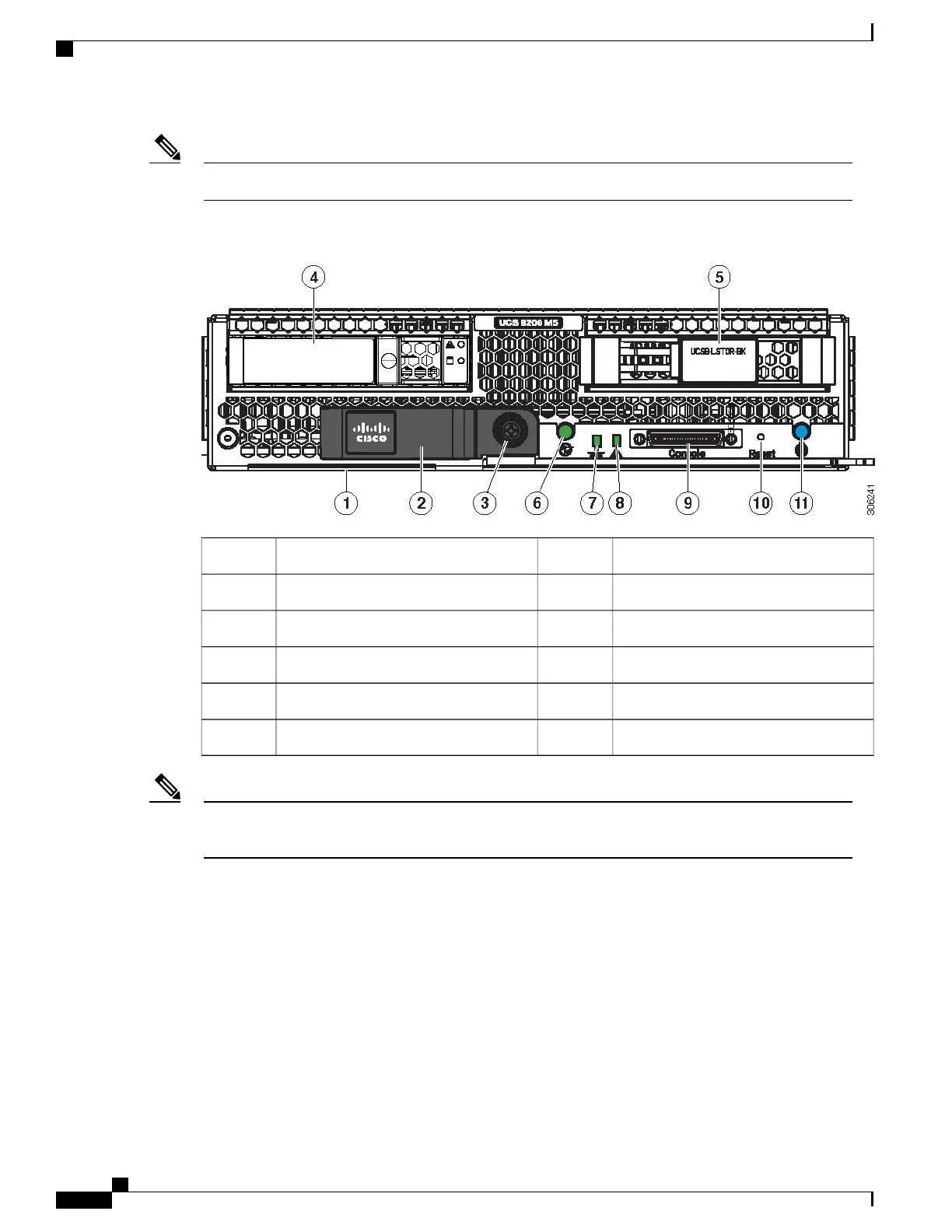
Figure 1: Cisco UCS B200 M5 Blade Server Front Panel
Blade ejector handle2Asset pull tag1
Drive bay 14Ejector thumb screw3
Power button and LED6Drive bay 25
Blade health LED8Network link status LED7
Reset button10Local console connection9
-Locate button and LED11
The asset pull tag is a blank plastic tag that pulls out from the front panel. You can add your own asset
tracking label to the asset pull tag and not interfere with the intended air flow of the server.
Note
External Features Overview
The features of the blade server that are externally accessible are described in this section.
LEDs
Server LEDs indicate whether the blade server is in active or standby mode, the status of the network link,
the overall health of the blade server, and whether the server is set to give a blinking blue locator light from
the locator button.
Cisco UCS B200 M5 Blade Server Installation and Service Note
2
Overview
External Features Overview
 Loading...