3-2
Cisco UCS C220 M4 Server Installation and Service Guide
OL-32473-01
Chapter 3 Maintaining the Server
Status LEDs and Buttons
Status LEDs and Buttons
This section describes the location and meaning of LEDs and buttons and includes the following topics
• Front Panel LEDs, page 3-2
• Rear Panel LEDs and Buttons, page 3-4
• Internal Diagnostic LEDs, page 3-6
Front Panel LEDs
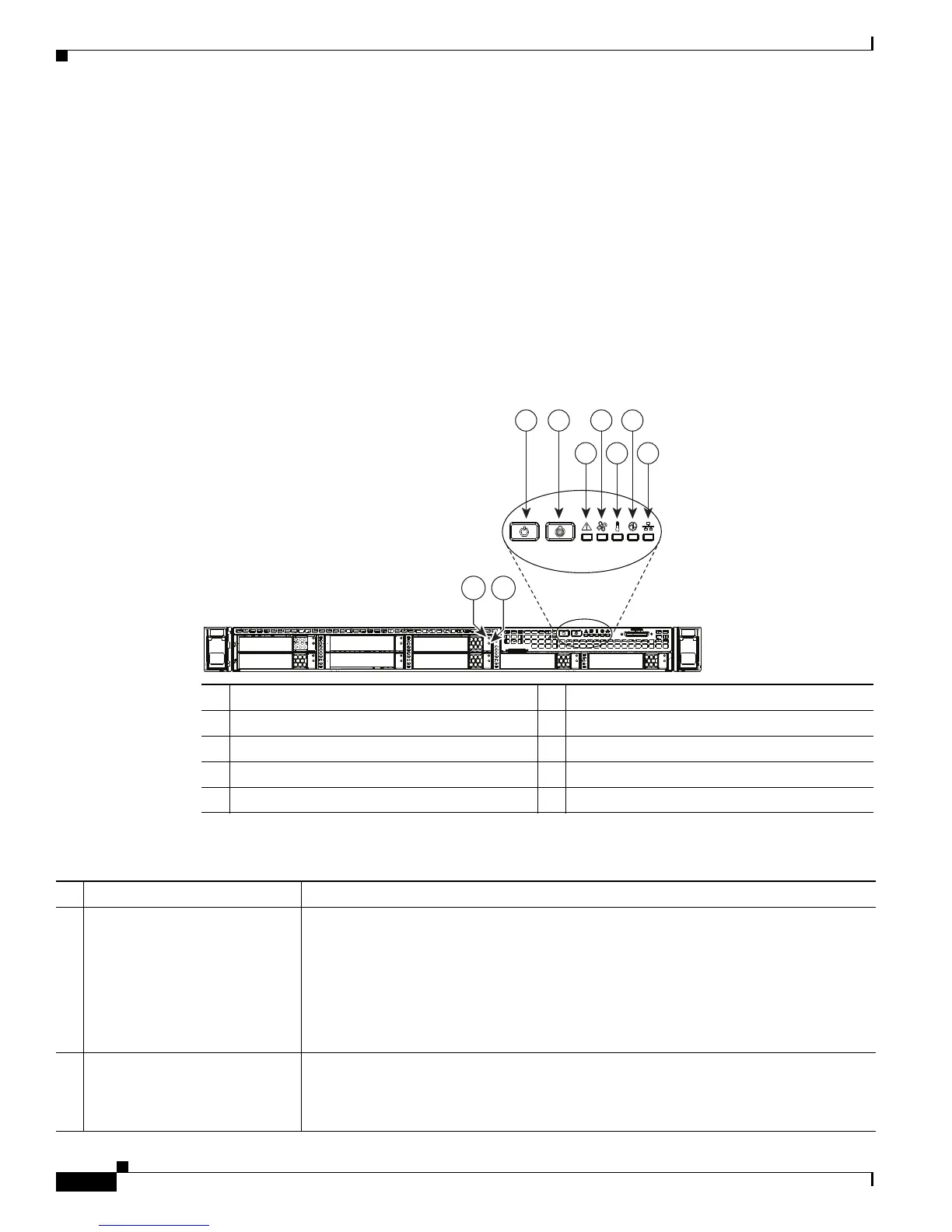
Figure 3-1 shows the front panel LEDs. Table 3-1 defines the LED states.
Figure 3-1 Front Panel LEDs
1 Hard drive fault LED 6 Fan status LED
2 Hard drive activity LED 7 Temperature status LED
3 Power button/power status LED 8 Power supply status LED
4 Identification button/LED 9 Network link activity LED
5 System status LED
Table 3-1 Front Panel LEDs, Definitions of States
LED Name State
1 Hard drive fault
Note: If your controller is a
Cisco UCS RAID SAS 9300-8i
or 9300-8e HBA, see Cisco UCS
SAS 9300-8e HBA
Considerations, page C-4 for
differing LED behavior.
• Off—The hard drive is operating properly.
• Amber—Drive fault detected.
• Amber, blinking—The device is rebuilding.
• Amber, blinking with one-second interval—Drive locate function activated.
2 Hard drive activity
• Off—There is no hard drive in the hard drive tray (no access, no fault).
• Green—The hard drive is ready.
• Green, blinking—The hard drive is reading or writing data.
353088
975
3 4 6 8
HDD 02
HDD 01 HDD 03
HDD 04
HDD 05
HDD 06
HDD 08
HDD 07
21
 Loading...


