Cisco UCS C480 M5 Memory Guide
Physical Layout
13
Physical Layout
Each CPU has six channels:
■ CPU1 and CPU3 have channels A, B, C, D, E, and F
■ CPU2 and CPU 4 have channels G, H, J, K, L, and M
Each channel has two slots: slot 1 and slot 2. The blue-colored DIMM slots are for slot 1 and the black slots
for slot 2.
As an example, slots A1, B1, C1, D1, E1, and F1 belong to slot 1, while A2, B2, C2, D2, E2, and F2 belong to
slot 2.
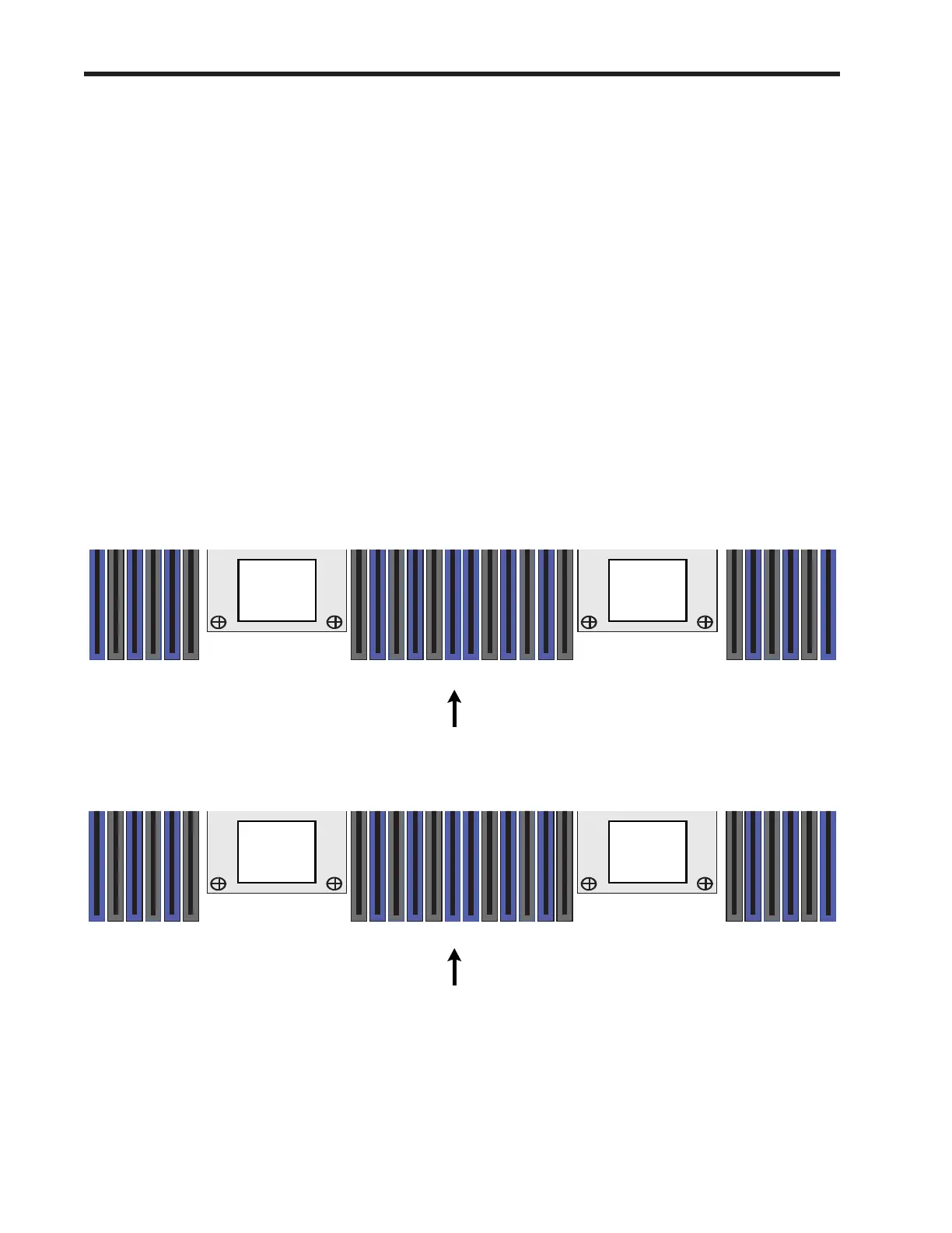
Figure 3 shows how slots and channels are physically laid out on the motherboard. The slots on the right
half of the motherboard (channels A, B, C, D, E, and F) are associated with CPU 1 for the lower bay and CPU
3 for the upper bay, while the slots on the left half of the motherboard (channels G, H, J, K, L, and M) are
associated with CPU 2 for the lower bay and CPU 4 for the upper bay. The slot 1 (blue) slots are always
located farther away from a CPU than the corresponding slot 2 (black) slots. Slot 1 slots (blue) are
populated before slot 2 slots (black).
Figure 3 Physical Layout of C480 M5 CPU Channels and Slots
Front of Lower CPU Module (Bay 1)
CPU 2
CPU 1
A2
A1
B2
B1
C2
C1
F1
F2
E1
E2
D1
D2
G2
G1
H2
H1
J2
J1
M1
M2
L1
L2
K1
K2
Front of Upper CPU Module (Bay 2)
CPU 4
CPU 3
A2
A1
B2
B1
C2
C1
F1
F2
E1
E2
D1
D2
G2
G1
H2
H1
J2
J1
M1
M2
L1
L2
K1
K2
Top View
Top View
 Loading...