INSTALLATION AND
CONNECTION
WIRE
1. BEFORE STARTING
1. This set is exclusively for use in vessels with
a negative ground 12 V power supply.
2. Read these instructions carefully.
3. Be sure to disconnect the battery “ ” terminal
before starting. This is to prevent short circuits
during installation. (Figure 1)
2. INSTALLATION CAUTIONS
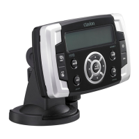
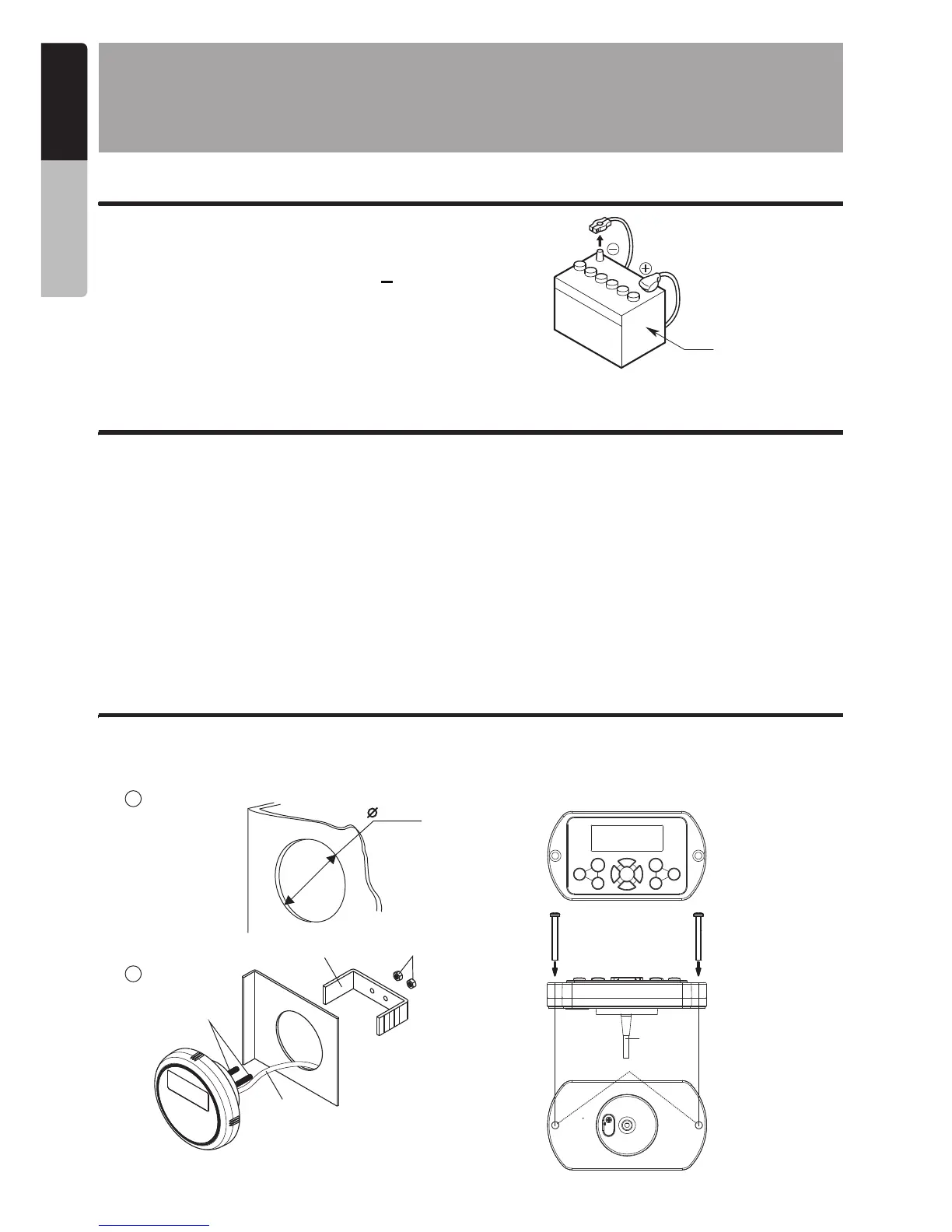
3. OPTIONAL MARINE WIRED REMOTE INSTALLATION
Battery
Figure 1
1. In order to avoid any interference, do not install the tuner module or control unit in the proximity of
the engine compartment.
2. The use of unauthorized parts can cause permanent damage to the unit.
3. Always check your wire connections to ensure proper installation before turning on the unit.
4. Consult with your nearest dealer for proper installation or if common parts need to be used.
Seek assistance if modifications or drilling holes to your vessel is needed.
5. Do not install the unit where it will be subjected to excessive moisture, dust, dirt, foreign particles
or vibration. Areas of high temperature from the engine, direct sunlight, heater or hot air should
also be avoided.
6. Do not install the unit in a location where it will interfere with the vessel operation, or it will injure the
passengers if there is a sudden or emergency stop.
The control unit should be mounted to a dry, clean and flat surface. Ensure the rear gasket is fully
sealed to the mounting surface without distorting the unit.
18
English
Owner’s Manual
CMS3
Screw Hole
MW1
MW3
8-Pin DIN Cable
Make the mounting
hole as follows.
1
3 1/8 Inch
2
Metal Bracket
M4 Nut
Hex Head
Screw 4x30
8-Pin
DIN Cable
 Loading...