 Loading...
Do you have a question about the Clarion CX501 and is the answer not in the manual?
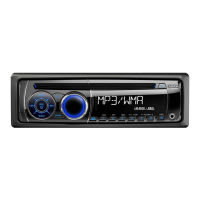
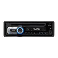
| MP3 playback | Yes |
|---|---|
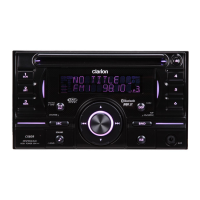
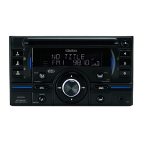
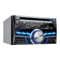
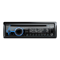
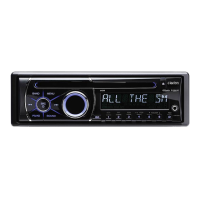
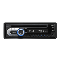
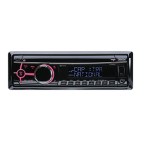
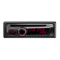
| Product color | Black |
| Volume control | Digital |
| USB version | 2.0 |
| Bluetooth profiles | A2DP, AVRCP, HFP, HSP, OPP, PBAP |
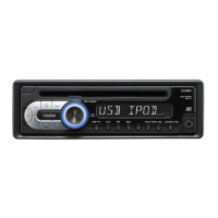
| USB ports quantity | 1 |
| Amplifier output power | 200 W |
| Key illumination color | Blue |