9. INSTALLATION
I
WIRE
,~
CONNECTION GUIDE
CONTENTS
1 ) Before Starting ...................................................................... 19
2)
Package
Contents ................................................................. 19
3)
General
Cautions .................................................................. 19
4)
Cautions
on
Installation
......................................................... 19
5)
Installing the Source Unit ...................................................... 19
6)
Removing the Source Unit ....................................................
20
7)
Wiring and Connections ........................................................
21
8)
Connecting the accessories ..................................................
21
1) Before
Starting
1.
This set is exclusively for use with a negative
ground 12 V power supply.
2.
Read these instructions
carefully.
3.
Be sure to disconnect the battery
"terminal"
before
starting. This is to prevent
short circuits during
installation.
(Figure
1)
2)
Package Contents
Figure 1
Battery
Source unit .....................
..
...................
..
.
..
.
..
1
Owner's manual. ........
..
.................
..
............. 1
Front
panel ..................................................
1
Trim ring
...
...................................................
1
Mounting bracket.. ...........
...
...
...
..........
..
.......
1
Hole block seal (black)
.
..
...
...............
...
.
.. ..
.
..
1
L-key ........
..
...........
..
....
...
..............................
2
Power
supply cable
......
..
.............................
1
DCP
case .................................................... 1
3)
General
Cautions
1.
Do not open the case. There are no
user serviceable parts inside.
If
you
drop anything into the unit during
installation, consult your dealer or
an
authorized
Clarion
service center.
Warranty card ..........
...
..................
...
............
1
Special
screw
(M1.6*5mm,front
panel lock)
.....
1
Screws M5x6 mm
Double Sems
................. 4
Screws M4x5 mm
Double Sems
............
.. ..
.
1
Strap .......
..
.................
...
...............................
1
M4 Washer ...................................
..
.............
2
M4 Nut
...
...................................................... 1
2.
Use a soft, dry
cloth
to
clean
the case.
Never use a rough cloth,
thinner,
benzine, or alcohol etc. For tough dirt,
apply a little cold or warm water to a
soft
cloth
and wipe off the dirt gently.
4)
Cautions on
Installation
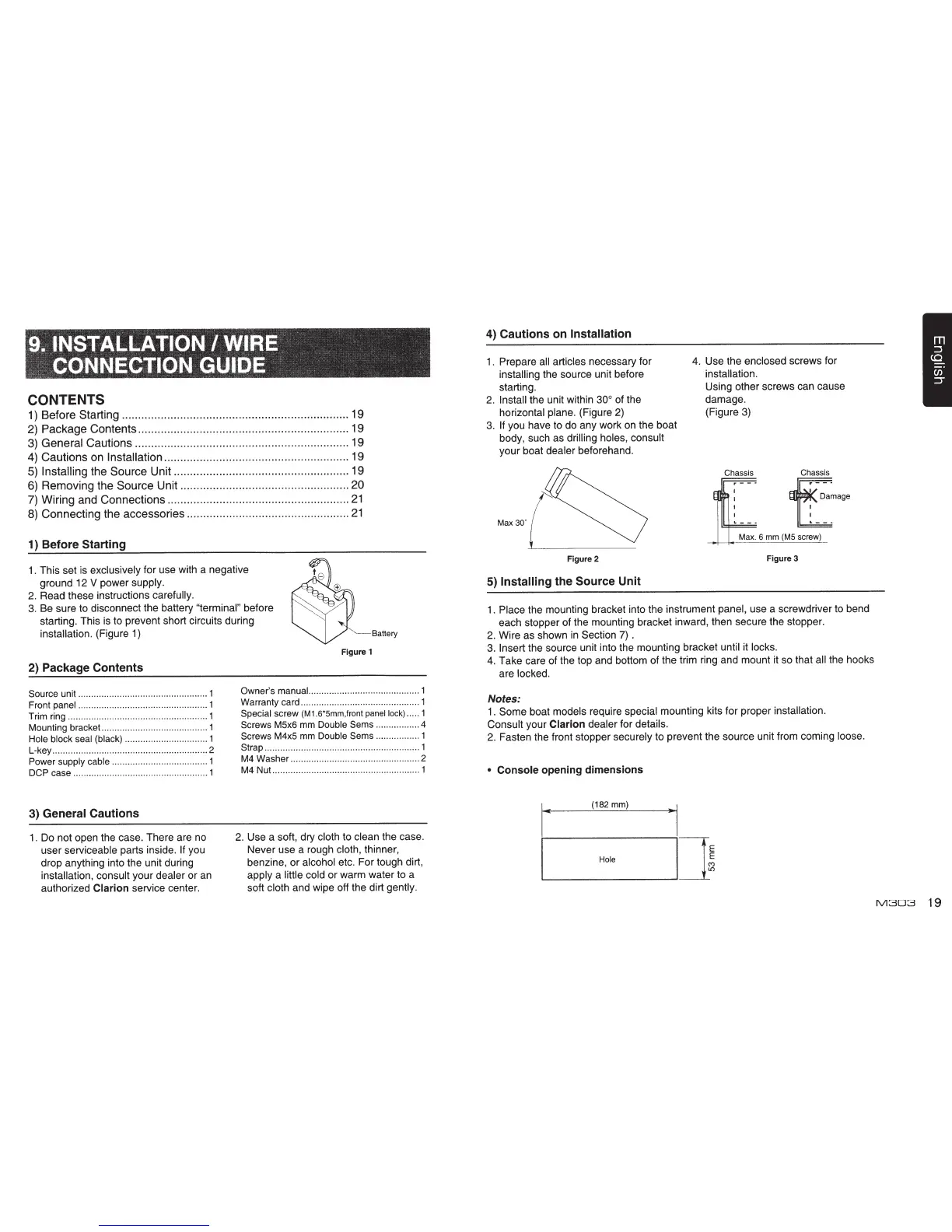
1 . Prepare
all articles necessary for
installing
the source unit before
starting.
2.
Install the unit within
30°
of the
horizontal plane. (Figure 2)
3.
If
you have to do any work on the boat
body, such as
drilling
holes, consult
your boat dealer beforehand.
Max
30'
Figure 2
5) Installing the
Source Unit
4.
Use the
enclosed
screws for
installation.
Using other screws can cause
damage.
(Figure 3)
Chassis Chassis
t~a~age
Max. 6
mm
(MS
screw)
Figure 3
1.
Place the mounting bracket into the instrument panel, use a screwdriver to bend
each stopper of the mounting bracket inward, then secure the stopper.
2.
Wire as shown
in
Section
7).
3.
Insert
the source unit into the mounting bracket until it locks.
4.
Take care of the top and bottom of the trim ring and mount it so that
all
the hooks
are locked.
Notes:
1.
Some boat models require special mounting kits for proper
installation.
Consult your
Clarion
dealer for details.
2. Fasten the front stopper securely to prevent the source unit from coming loose.
•
Console
opening
dimensions
I"'
(182mm)
..
1
I.._____Hole
~~]~
M303
19

 Loading...