pag 13
CONDENSATE DISCHARGE CONNECTION
.
1. The condensate must be dispersed to avoid damages to persons and
property.
2. Unit discharge fitting : the connection must avoid the transmission of
mechanical stresses and must be performed paying attention to avoid the
damaging of the unit discharge fitting
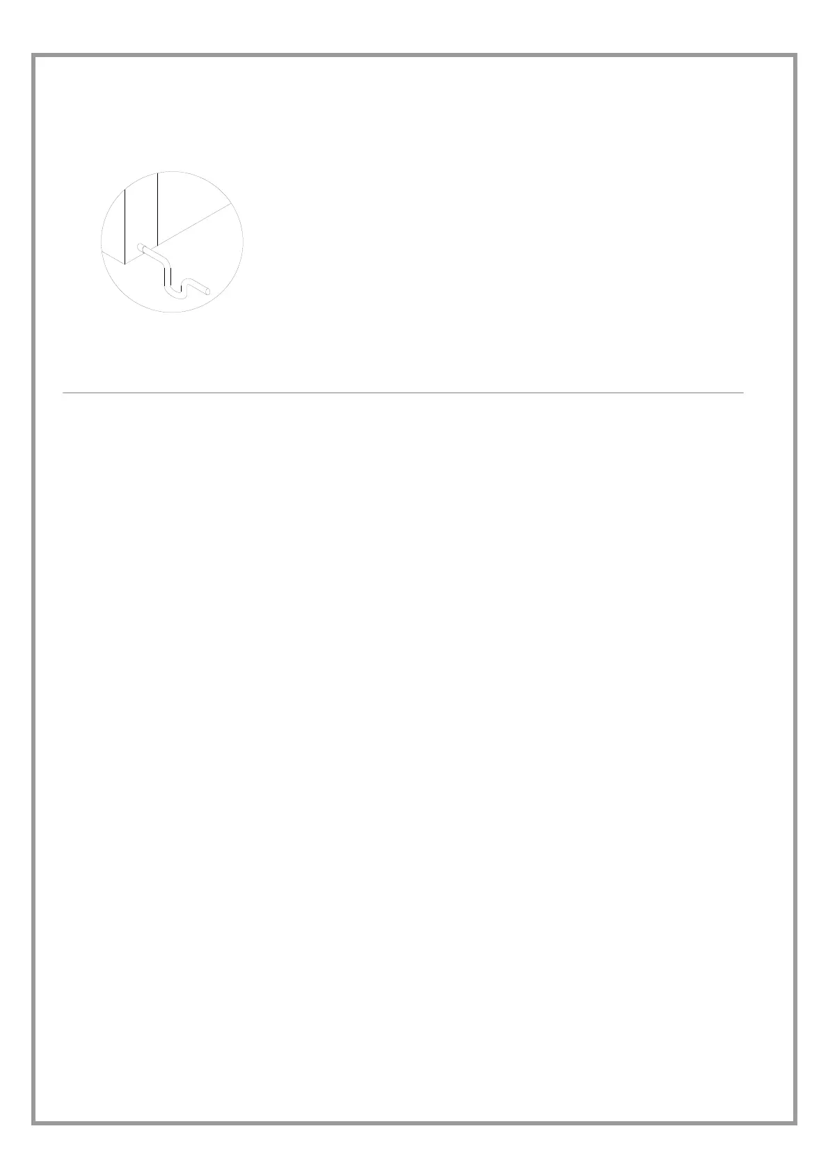
3. Make a trap that, eliminating the depression caused by the fan, stops the
return of gas from the discharge pipe (see the figure).
4. Connect the condensate discharge to a rainwater drain. Do NOT use
sewerage drains, so as to avoid the return of odours if the water contained in
the trap evaporates.
5. Finally, check that the condensate will drain correctly by pouring water into the
tray stud.
6. RISK OF FREEZE : If the unit operates in cooling with external temperatures
lower than 0°C, value the possibility that the condensate can freeze blocking
the downflow and provoking flooding. Use heat cables or other devices to
guarantee the disposal.
WATER HEATING COIL
OPTIONAL - The position of the connections is shown on
the dimensional drawing of the unit.
The air valve is placed on the top of the coil manifold, it is
used to eliminate possible air bubbles on the circuit.
The discharge valve is placed on the bottom of the
manifold, it is used to empty the coil if it is unused for a
long period.
TO AVOID THE FREEZE FORMING INSIDE THE COIL
1. If the unit or the relevant water connection are
subjects to temperatures next to 0°C see RISK OF
FREEZE in the GENERAL WARNINGS paragraph.
2. The freeze forming is possible also in summer in
abnormal operating conditions (ex. Insufficient air
flow-rate for clogged filters). It is so recommended to
glycolate or empty also in summer
HUMIDIFIER
WATER SUPPLY
The humidifier is to be supplied with mains water with the
following characteristics:
pressure inclusive between 0.1 and 0.8 Mpa (1–8bar)
temperature inclusive between 1 and 40°C
Do not use:
softened water: it may cause corrosion of the
electrodes and foaming resulting in
malfunctions/failures
well water, industrial water, or any other water which
may be contaminated (by chemicals or bacteria)
disinfectant or anti-corrosion substances mixed with
the water, as they are potential irritants
DRAINAGE WATER
may reach a temperature of 100 °C
contains the same substances as the water supply but
in greater concentrations
it is not toxic and may be disposed of with clear water
RISK OF ICING:
insulate the pipes
empty in case of extended periods of disuse
provide anti-freeze heating element in case of
especially severe temperatures
AIR CONNECTIONS
Proper execution and sizing of air connections are essential
for ensuring correct operation of the unit and an acceptable
level of silence in the room.
When designing and creating ducts, consider PRESSURE
DROPS, FLOW RATE and AIR SPEED which need to be
compatible with the characteristics of the unit. Special
consideration needs to be made for pressure drops that are
greater than the unit's static pressure, which would lead to
a reduction in flow rate resulting in unit shutdown.
the weight of the ducts must not be supported by the
connection flanges
place anti-vibration joints between the ducts and the
unit
the connection to the flanges and between the various
sections of the ducts must ensure an airtight seal,
preventing leakage in delivery and intake which would
compromise overall system efficiency.
for units installed outdoors, the connection to the
flanges and between the various duct sections must be
watertight (external unit only - do not print note)
limit pressure drops by optimizing the path, the type
and number of curves and the branches
use curves with a wide radius. Consider whether it
might be useful to equip them with deflectors
(especially if the air speed is high or if curves are tight)
 Loading...