pag 18
IF THE CRANKCASE HEATERS ARE FITTED
when the unit is started up for the first time and following
all prolonged periods of inactivity is OBLIGATORY to
connect the oil heaters on the compressor crankcase at
least 8 hours before the compressor is to be starter.
BEFORE POWERING THE HEATERS, OPEN THE
COMPRESSORS COCKS, IF PRESENT.
To supply the heaters is necessary to switch off the
isolator switch on the unit.
To make sure that hte heaters are working, check the
power input with amperometic pliers.
At start-up the compressor cranckase temperature on the
lower side must be higher at least of 10°C than the
external temperature.
DO NOT START THE COMPRESSOR WITH THE
CRANKCASE OIL BELOW OPERATING
TEMPERATURE.
VERIFY TENSIONS – ABSORPTIONS
Check that the temperatures of the fluids are included in
the WORKING LIMITS.
If the controls of the previous paragraphs are positive, it is
possible to restart the unit.
For information on the control panel, refer to the paragraph
CONTROL.
While the unit is working (ATTENTION ELECTRIC RISK:
WORK SAFETLY) check:
• Power supply tension
• Phase unbalance
• Total absorption of the unit
• Absorption of the single electric loads
UNIT EQUIPPED WITH SCROLL COMPRESSORS
The GENERAL TECHNICAL DATA table shows the type
of compressor on the unit.
The Scroll compressors have only one direction of
rotation.
In the event that the direction is reversed, the compressor
will not be damaged, but its noisiness will increase and
pumping will be negatively affected. After a few minutes,
the compressor will stop because of the activation of the
thermal protection. In this event, cut the power and
reverse the 2 phases on the machine power.
Prevent the compressor from working with in reverse
rotation: more than 2-3 anomalous starts up can damage
it.
Make sure the direction of rotation is correct, measure the
condensation and suction pressure. Pressure must clearly
differ: at the start, the suction pressure decreases whilst
the condensation pressure increases.
The phase optional monitor, which controls the phase
sequence, can be installed later.
REMOTE INPUT CONFIGURATIONS
Check used remote inputs are activated (ON-OFF etc.) as
given in the instructions in the ELECTRIC WIRING
chapter.
SETTING THE SET-POINT
Check if it is necessary to modify the set-points shown in
the CONTROL chapter
AIR FLOW CHECK
The effective unit flow-rate is function of the aeraulic
system characteristics.
It is so necessary to check the air flow-rate and eventually
to proceed with the appropriate calibrations on the system
(dampers, diffusers etc) and on the unit (fan speed control,
pulley calibrations etc in base of the unit type and its
configuration). Before performing the check, make sure
that the system has been completed in all its parts
(derivations, dampers, grilles, diffusers etc) .
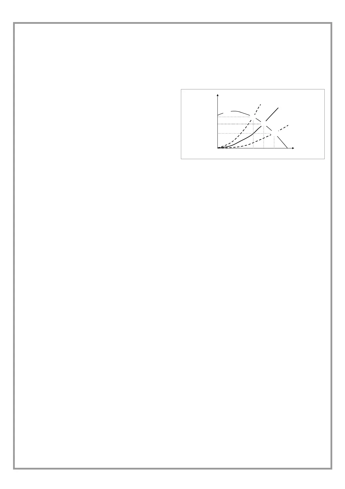
D = unit head-flow rate curve
A = system calculated curve
1 = project theorical working point
3 = if the system has pressure drop lower than the project
ones, the working point will be the 3,with flow-rate
higher that the project one
2 = if the system has pressure drop higher than the project
ones, the working point will be the 2, with flow-rate
lower that the project one
In the time the working point can change, for example for
the operations on the system (grilles covered by furniture,
closed outlets to modify the air diffusion, exclusion or
addition of the distribution sections etc.) or for lacking
maintenance (clogged air filters, blocked dampers etc) .
REFRIGERANT CIRCUIT PARAMETER CHECK
Detecting the operational conditions is useful to control the
unit along time: the performed records must be kept and
be available during maintenance interventions.
When the unit works in stable conditions and according to
the operating limits, take note of the following data:
1. compressor diacharge temperature (WARNING –
BURN DANGERI)
2. condensing pressure
3. liquid temperature
4. dehydrator filter upstream and downstream
temperature
5. return pressure
6. return temperature
7. return air temperature
8. supply air temperature
9. external air temperature (coil input)
10. air temperature coming out from fans
Pa
L/sec
1
2
3
B
C
D
 Loading...