pag 14
ELECTRICAL CONNECTION
GENERAL
The characteristics of the electrical lines and relevant
components must be determined by SPECIALIZED
PERSONNEL ABLE TO DESIGN ELECTRICAL
INSTALLATIONS; moreover, the lines must be in
conformity with professional procedures and the regulations
in force.
All electrical operations should be performed by trained
PERSONNEL HAVING THE NECESSARY REQUISITES
UNDER LAW and being informed about the risks relevant
to these activities.
Before performing any operation on the electrical system,
make sure that the unit supply line is SELECTED AT
START.
The earth connection must be made prior to other electrical
connections.
For all electrical type operations, REFER TO THE
ELECTRICAL DIAGRAM ATTACHED TO THE UNIT; the
number of the diagram is shown on the registration plate
positioned on the electrical board or next to it.
The electrical diagram should be carefully kept together
with this manual and should be AVAILABLE FOR FUTURE
INTERVENTION ON THE UNIT.
LINE OF UNIT POWER SUPPLY
The ELECTRICAL DATA OF THE UNIT are shown in the
technical chart of this manual and on the unit registration
plate. The presence of accessories can vary according to
the unit; the electrical data shown in the technical chart
refer to standard units. In the event of differences between
the data of the registration plate and the data shown in this
manual, as well as in the technical chart, please refer to the
DATA SHOWN IN THE REGISTRATION PLATE.
The protection device of the unit power supply line should
break off the short circuit power whose value should be
determined according to the plant features.
The section of supply cables and protection cable must be
seized according to the characteristics of the protections
used.
SIGNALS / DATA LINES
Do not overpass the maximum power allowed, which
varies, according to the type of signal.
Lay the cables far from power cables or cables having a
different tension and that are able to emit electromagnetic
disturbances.
Do not lay the cable near devices which can generate
electromagnetic interferences.
Do not lay the cables parallel to other cables; cable
crossings are possible, only if laid at 90°.
Connect the screen to the ground, only if there are no
disturbances
Assure the continuity of the screen during the entire
extension of the cable.
Observe, if any, the requirements about impendency,
capacity, attenuation
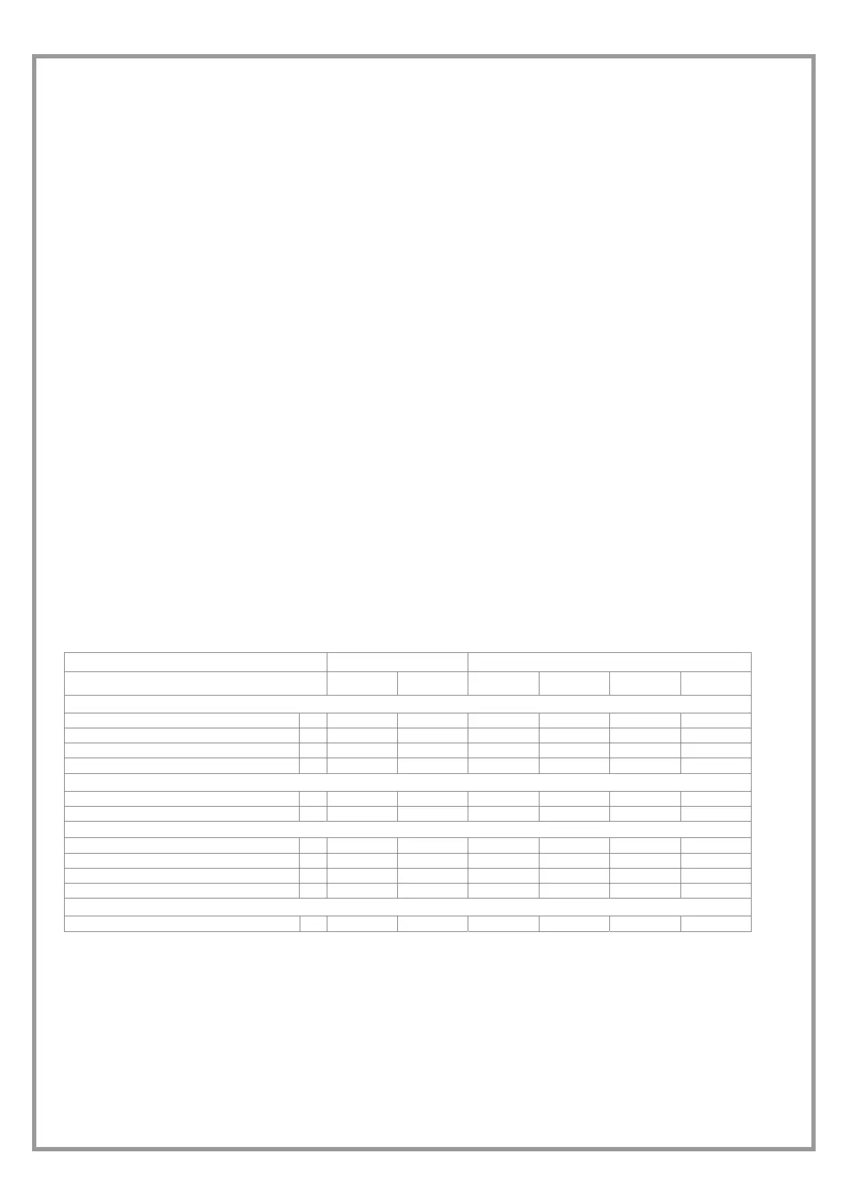
STANDARD UNIT ELECTRICAL DATA
Voltage 230/1/50 400/3/50 + NEUTRAL
Size 17 21 25 31 41 51
F.L.A. Full load current at max admissible conditions
F.L.A. - Compressor 1 A 8,6 10,7 11 5,4 8 10,3
F.L.A. - Single Outlet fan A 2,4 2,4 5 5 4,6 6,7
F.L.A. - Single exhaust air fan A 2,4 2,4 5 5 4,6 6,7
F.L.A. – Total A 13,4 15,5 21 15,4 17,2 23,7
L.R.A. Locked rotor amperes
L.R.A. - Compressor 1 A 43 62 62 43 48 64
L.R.A. - Single Outlet fan A 12 12 25 25 29,5 34
F.L.I. Full load power input at max admissible condition
F.L.I. - Compressore 1 kW 1,9 2,4 2,5 3,1 4,3 6,1
F.L.I. - Single Outlet fan kW 0,3 0,3 0,37 0,37 0,55 0,55
F.L.I. - Single exhaust air fan kW 0,3 0,3 0,37 0,37 0,55 0,55
F.L.I. - Total kW 2,5 3 3,3 3,8 5,4 7,2
M.I.C. Maximum inrush current
M.I.C. - Value A 67 86 112 93 107 132
Power supply: 230/1/50 Hz +/-6%
Power supply: 400/3/50 Hz +/-6%
voltage unbalance: max 2 %
Values not including accessories
 Loading...