6
General Details
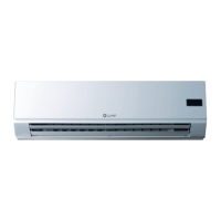
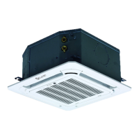
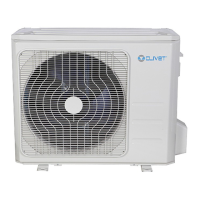
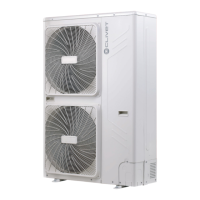
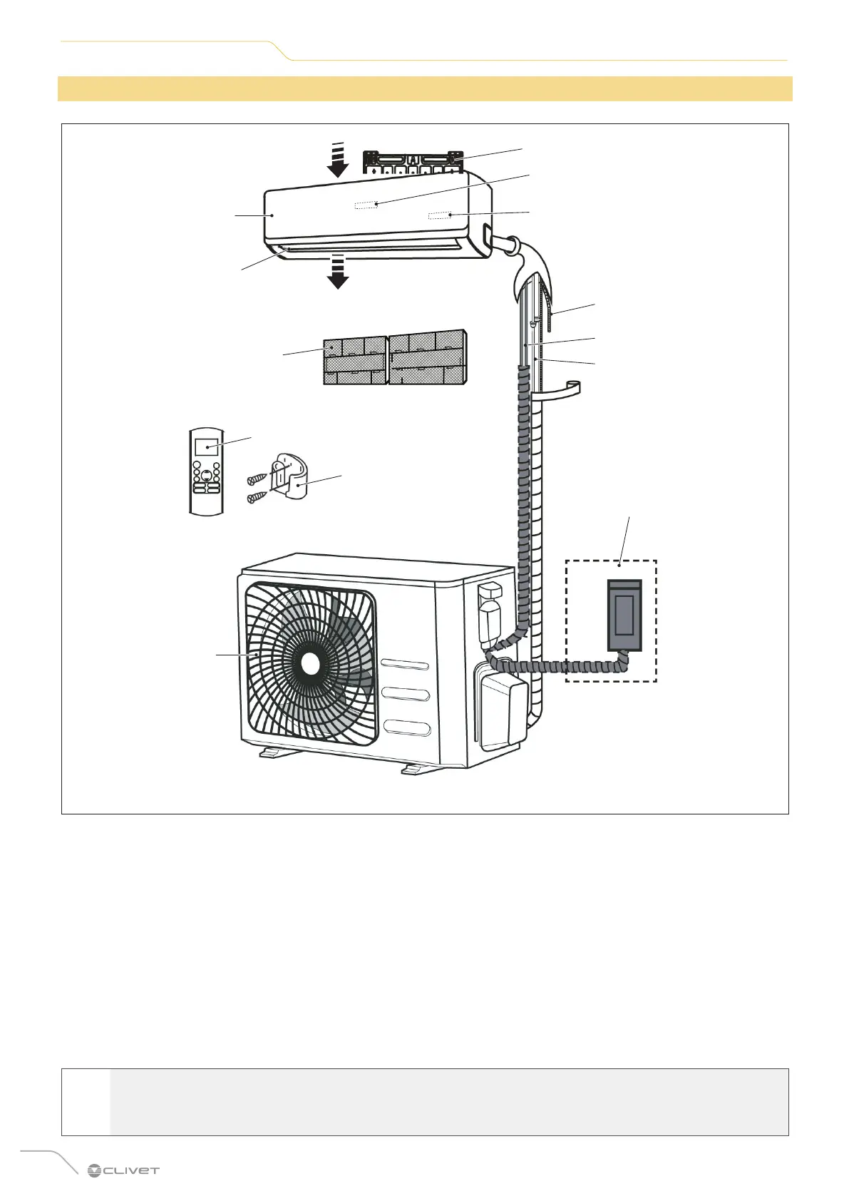
1.2 Description of system components
12
13
2
A
B
5
11
6
9
7
8
10
3
4
Fig. 1
A Air inlet
B Air outlet
1 Wall mounting plate
2 Indoor unit
3 Ventilation louver
4 Filter
5 Outdoor unit
6 Flexible drainage hose
7 Electrical connection
8 Refrigerant piping
9 Outdoor unit power supply
10 Remote control
11 Remote control support
12 Display led CRISTALLO
13 Display led ESSENTIAL 2
l
WARNING
The images in this manual are provided for illustrative purposes only. The appearance of your device may
dier slightly from the illustrations shown here. Refer to the actual characteristics of the unit.
 Loading...