EasyManuals Logo
Home>Crestron>Transmitter>DM-TX-201-C

Crestron DM-TX-201-C Supplemental Guide

Crestron DM-TX-201-C
18 pages
To Next Page IconTo Next Page
To Previous Page IconTo Previous Page
Page #15 background imageLoading...
Page #15 background image
Supplemental Guide Doc. 6958E DM-TX-201-C 11
Appendix: Pin Assignments
This section provides information about pin assignments and wiring for the following
connectors:
l RGB IN
l DM OUT
l LAN
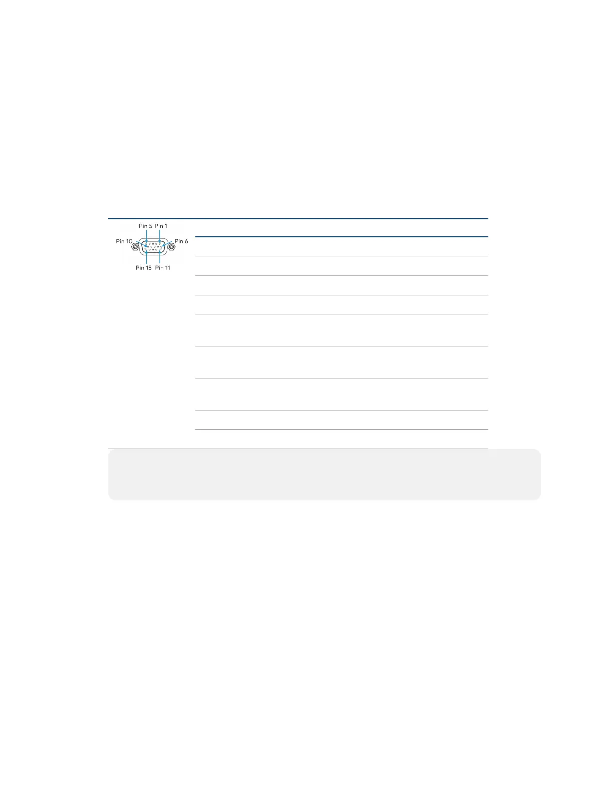
RGB IN Pin Assignments
PinNumber RGB YPbPR S-Video Composite
1 R Pr C
2 G Y Y
3 B Pb COMP
5 GND GND GND GND
6 RED_
GND
PR_
GND
C_
GND
7 GRN_
GND
Y_
GND
Y_
GND
8 BLU_
GND
Pb_
GND
13 H
14 V
NOTE: For best video performance, ground connections should be kept separate. Do
not connect ground wires to the connector shell. The connector shell is reserved for the
cable shield.

Other manuals for Crestron DM-TX-201-C

Questions and Answers:

Question and Answer IconNeed help?

Do you have a question about the Crestron DM-TX-201-C and is the answer not in the manual?

Crestron DM-TX-201-C Specifications

General IconGeneral
TypeNetwork transmitter
Duplex systemFull, Half
Auto-negotiationYes
Ethernet LAN data rates10, 100 Mbit/s
Maximum transfer distance- m
Cabling technology10/100Base-T(X)
Networking standardsIEEE 802.3at
RJ-45 ports quantity (transmitter)2
Product colorBlack
Output current0.75 A
Output voltage24 V
AC input voltage100-240 V
AC input frequency50 - 60 Hz
Operating temperature (T-T)0 - 40 °C
Operating relative humidity (H-H)10 - 90 %
Weight and Dimensions IconWeight and Dimensions
Depth32 mm
Width187 mm
Height165 mm
Weight721 g

Related product manuals