Supplemental Guide — Doc. 6958E DM-TX-201-C • 3
Ê
LAN: 8-pin RJ-45 female, shielded, with two LED indicators;
10BASE-T/100BASE-TX Ethernet port;
Green LED indicates Ethernet link status;
Amber LED indicates Ethernet activity
Ë
DM OUT: 8-pin RJ-45 female, shielded, with two LED indicators;
DM 8G+ output, HDBaseT compliant;
PoDM and HDBaseT PoE powered device (PD) port ;
Connects to the DM 8G+ input of a DM® switcher, receiver/room controller, or other
DM device, or to an HDBaseT device via CAT5e or Crestron DM-CBL-8G cable;
Green LED indicates DM link status;
Solid amber LED indicates HDCP video;
Blinking amber LED indicates non-HDCP video
NOTE: In order for the DM-TX-201-C to receive PoDM, the DM-TX-201-C requires
connection to a DM switcher or other DM equipment that has a PoDM power
sourcing equipment (PSE) port. In order for the DM-TX-201-C to receive
HDBaseT PoE, the DM-TX-201-C requires connection to equipment that has an
HDBaseT PoE PSE port. Any wiring that is connected to a PoDM or HDBaseT PoE
port is for intrabuilding use only and should not be connected to a line that runs
outside of the building in which the PSE is located.
Ì
HDMI OUT: 19-pin Type A HDMI female connector;
HDMI digital video/audio output (DVI compatible);
NOTE: The HDMI OUT connection requires an appropriate adapter or interface
cable to accommodate a DVI or Dual-Mode DisplayPort™ signal. CBL-HD-DVI
interface cables are available separately.
Í
PWR 24 VDC 0.75 A: 2.1 x 5.5 mm DC power connector;
24 VDC power input;
Optional PW-2407WU power pack (sold separately)
Î
Power LED: Green LED, indicates operating power supplied from optional
PW-2407WU power pack, PoDM, or HDBaseT PoE
Ï
Ground ( ): 6-32 screw, chassis ground lug
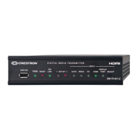
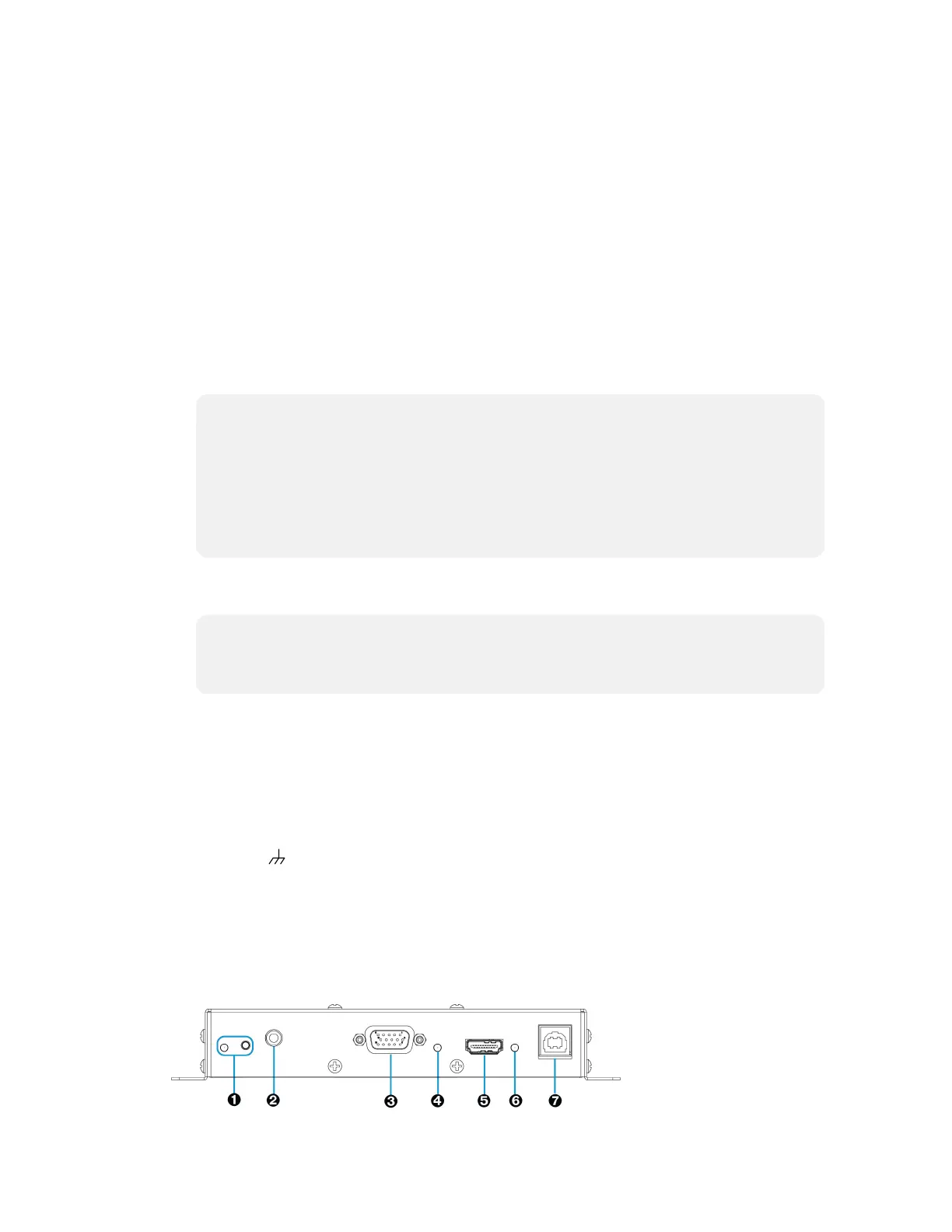
Rear View
The following illustration shows the rear of the DM-TX-201-C.
Rear View
 Loading...