AIR FILTER MAINTENANCE
Cleaning the Air Filter
Failure to maintain the air filter properly can
result in poor performance or can cause
permanent damage to the engine.
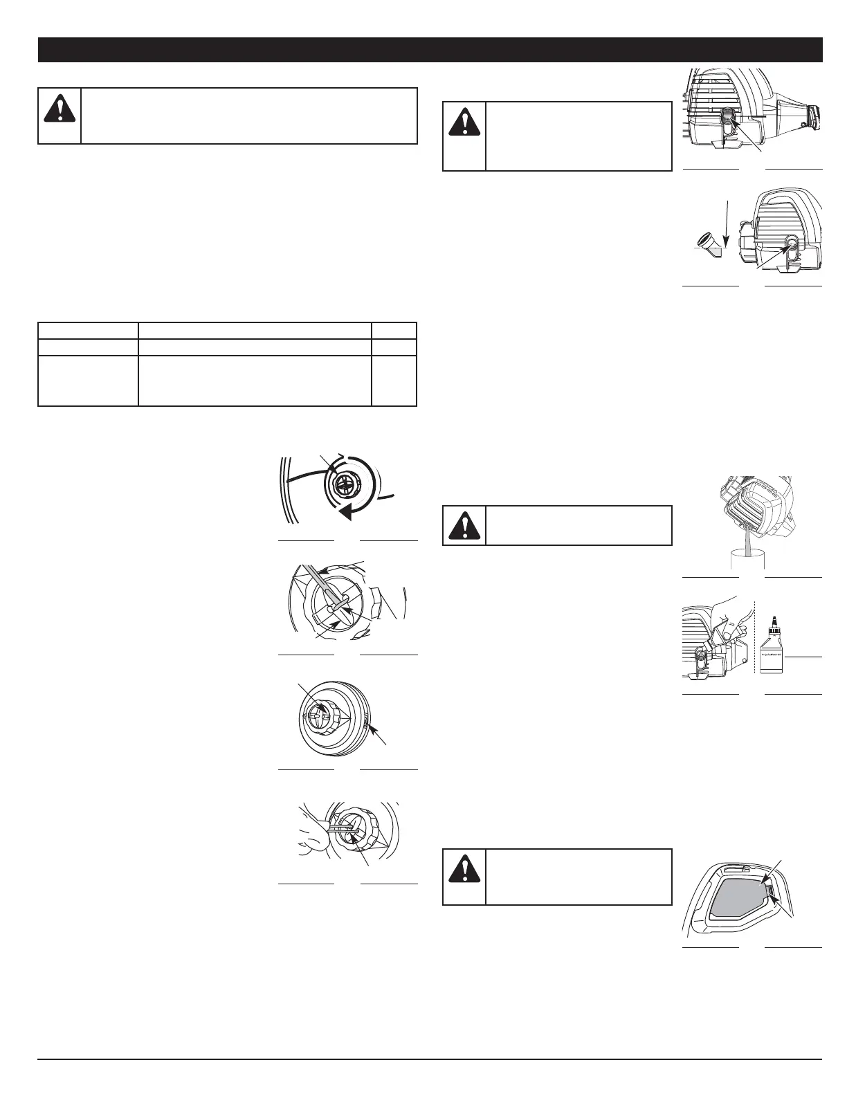
1. Open the air filter cover by pressing the lock tab in and pulling out on the
air filter cover (Fig. 39 & 40).
2. Remove the air filter (Fig. 41).
3. Wash the filter in detergent and water. Rinse the filter thoroughly and
allow it to dry.
4. Apply enough clean SAE 30 motor oil to lightly coat the filter.
CHANGING THE OIL
Change the oil while the engine is still warm. The
oil will flow freely and carry away more impurities.
1. Remove the oil fill plug.
2. Pour the oil out of the oil fill hole and into a
container by tipping the unit to the side (Fig.
37). Allow ample time for complete drainage.
3. Wipe up any oil residue on the unit and clean
up any oil that may have spilled. Dispose of
the oil according to federal, state and local
regulations.
4. Refill the crankcase with 2.2 fl.oz. (60 ml) of
SAE 30 SJ oil (Fig. 38).
NOTE: Use the bottle and spout saved from initial use to measure the
correct amount of oil. Check the level (Fig. 36). If the level is low,
add a small amount of oil and recheck. Do not overfill (Fig. 36).
5. Replace the oil fill plug.
CHECKING THE OIL LEVEL
The importance of checking and maintaining the
proper oil level in the crankcase cannot be
overemphasized. Check oil before each use:
1. Stop the engine and allow oil to drain into
the crankcase.
2. Place the unit on a flat, level surface to get a
proper oil level reading.
3. Keep dirt, grass clippings and other debris
out of the engine. Clean the area around the
oil fill plug before removing it.
4. Remove the oil fill plug (Fig. 35).
5. Check the oil level. Oil should be just to the bottom of the threads of the
oil fill hole (Fig. 36).
6. If the level is low, add a small amount of oil to the oil fill hole and recheck
(Fig. 36). Repeat this procedure until the oil level reaches the bottom of
the threads in the oil fill hole.
NOTE: Do not overfill the unit.
NOTE: Make sure the O-ring is in place on the oil fill plug when checking
and changing the oil.
REMOVING THE LINE
1. Rotate the bump knob clockwise until all line
is inside the cutting head (Fig. 31).
2. Using a flat-head screwdriver, insert the tip
into the line dimple and just under the
exposed portion of the line (Fig. 32)
3. Pull the line straight out until all line is
removed from the cutting head.
LINE INSTALLATION
Always use original equipment manufacturer
0.095 in. (2.41 mm) replacement line.
1. Align the arrows on the bump knob with the
spool cover eyelets, if they are not already
(Fig. 33).
2. Using 10 ft. (3 m) of 0.095 in. (2.41 mm)
replacement line push both ends of the line
through the holes in the bump knob until they
protrude through the eyelets on both sides of
the cutting head. Continue pulling the line
until approximately 5 ft. (1.5 m) is visible from
both sides of the cutting head. (Fig. 34)
3. Hold the spool cover, turn the bump knob
clockwise to wind the line around the spool
until about 5 in. (12.7 cm) is protruding from
each side of the cutting head. (Fig. 31)
4. Start the unit and bump the cutting head on
the ground until the desired cutting length is
achieved. Excess line will be trimmed off by
the line blade.
NOTE: If the cutting line ends are pulled into the
cutting head or the line becomes twisted, refer to Removing the Line.
10
MAINTENANCE AND REPAIR INSTRUCTIONS
CAUTION: Wear gloves to prevent
injury when handling the unit.
WARNING: To avoid serious
personal injury, always turn the unit
off and allow it to cool before you
clean or service it.
Oil Fill Hole
Fig. 36
Fig. 37
Fill
Level
Fig. 38
Air Filter
Cover Tab
Fig. 39
Air Filter Cover
MAINTENANCE SCHEDULE
Perform these required maintenance procedures at the frequency stated in
the table. These procedures should also be a part of any seasonal tune-up.
NOTE: Some maintenance procedures may require special tools or skills.
If you are unsure about these procedures take your unit to any
non-road engine repair establishment, individual or authorized
service dealer.
NOTE: Maintenance, replacement, or repair of the emission control
devices and system may be performed by any non-road engine
repair establishment, individual or authorized service dealer.
NOTE: Please read the California/EPA statement that came with the unit
for a complete listing of terms and coverage for the emissions
control devices, such as the spark arrestor, muffler, carburetor, etc.
WARNING: To prevent serious injury, never perform
maintenance or repairs with unit running. Always service and
repair a cool unit. Disconnect the spark plug wire to ensure that
the unit cannot start.
Flat-Head
Screw
Driver
Arrows
Trimmer
Line
Dimple
Eyelet
Trimmer line
Bump Knob
FREQUENCY MAINTENANCE REQUIRED SEE
Every 10 hours Clean and oil air filter p. 10
After the first 10
hours and every 40
hours
Change oil
Check rocker arm to valve clearance and adjust
Check spark plug condition and gap
p. 10
p. 11
p. 11
Fig. 34
Fig. 33
Fig. 32
Fig. 31
WARNING: To prevent extensive
engine wear and damage to the
unit, always maintain the proper oil
level in the crankcase. Never
operate the unit with a low oil level.
Fig. 35
Oil Fill Plug
Oil Fill Line
 Loading...