4
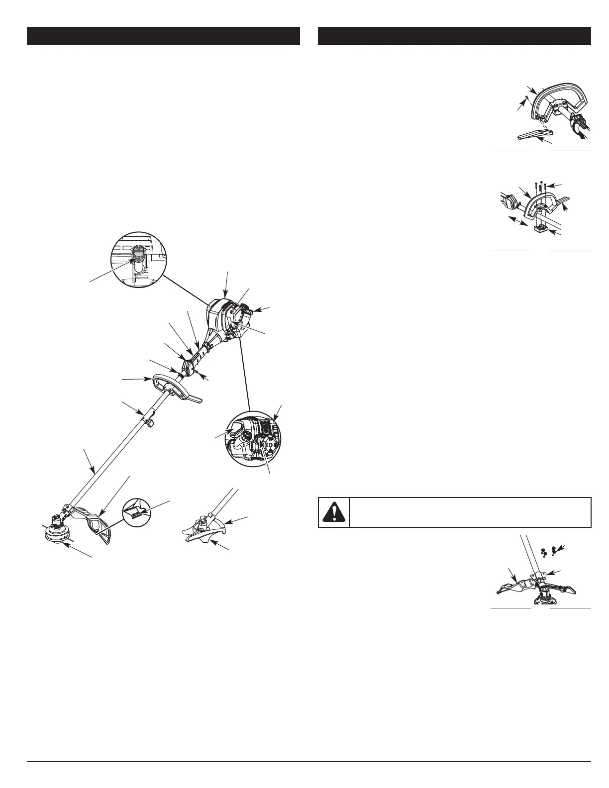
KNOW YOUR UNIT ASSEMBLY INSTRUCTIONS
INSTALLING AND ADJUSTING THE HANDLE
Installing the Barrier Bar
1. Align the two pegs on the barrier bar with
the two holes in the handle (Fig. 1).
2. Press the barrier bar into the handle until the
barrier bar snaps into place.
3. Insert the barrier bar screw into the handle
(Fig. 1).
4. Use a medium flat-head screwdriver or a T-
20 Torx® screwdriver to tighten the barrier
bar screw until the barrier bar is secure.
Installing the Handle
1. Remove the screws from the handle and
bottom clamp.
2. Place the handle above the shaft housing.
Place the bottom clamp below the shaft
housing. Align the handle and bottom clamp
(Fig. 2).
NOTE: Make sure the barrier bar points
toward the operator’s left side when
the unit is held in the operating position.
3. Insert the 4 screws through the handle and into the bottom clamp (Fig. 2).
Use a large flat-head screwdriver or a T-25 Torx screwdriver to partially
tighten the screws.
4. While holding the unit in the operating position, move the handle to the
location that provides the best grip. Place it a minimum of 6 inches (15.24
cm) from the end of the shaft grip (Fig. 2).
5. Tighten the screws until the handle is secure.
Adjusting the Handle
If the handle requires adjustment:
1. Use a large flat-head screwdriver or a T-25 Torx screwdriver to loosen the
4 screws in the handle.
2. While holding the unit in the operating position, move the handle to the
location that provides the best grip. Place it a minimum of 6 inches (15.24
cm) from the end of the shaft grip (Fig. 2).
3. Tighten the screws until the handle is secure.
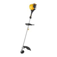
Cutting Head
Shield
Fuel
Cap
Throttle
Control
Handle
Cutting Head
Shaft Grip
Primer
Bulb
Choke Lever
Spark Plug
On/Off Stop Control
Shaft Housing
Starter
Rope Grip
Muffler
Air Filter
Cover
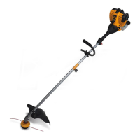
APPLICATIONS
As a trimmer:
• Cutting grass and light weeds.
• Edging
• Decorative trimming around trees, fences, etc.
As a brushcutter:
• Cut heavy grass and weeds up to 1/2” (1.3 cm) diameter.
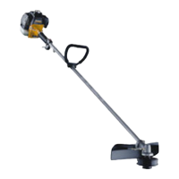
Rapid-Link™
Throttle Lock-out
Shoulder Strap Clip
TOOLS REQUIRED:
• Medium flat-head screwdriver or T-20 Torx® screwdriver
• Large flat-head screwdriver or T-25 Torx screwdriver
• Phillips screwdriver
• Locking Rod
• 7/16 inch closed-end or socket wrench
• 1/2 inch closed-end or socket wrench
Handle
Barrier Bar
Fig. 1
Barrier
Bar
Screw
Barrier
Bar
Handle
Fig. 2
Minimum 6 in.
(15.24 cm)
Screws
Bottom
Clamp
TRIMMER ASSEMBLY
Installing the Cutting Head Shield
Use the following instructions if the cutting head
shield is not installed. Use only the instructions
that apply to the type of shaft and shield
equipped with this unit.
1. Place the cutting head shield onto the mount
bracket. Align the holes in the cutting head
shield with the holes in the mount bracket.
(Fig. 3)
2. Screw the 2 screws through the mount
bracket and into the cutting head shield until finger tight.
3. Using a Phillips screwdriver, tighten the screws until the cutting head
shield is firmly in place.
WARNING: To prevent serious personal injury, never operate the
unit as a trimmer without the cutting head shield in place.
Fig. 3
Mount
Bracket
Screws (4)
Cutting
Head
Shield
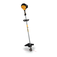
Line Cutting
Blade
Oil Fill Plug
Brush Cutter
Blade
Brush Blade
Guard
 Loading...