TRIMMER RE-ASSEMBLY
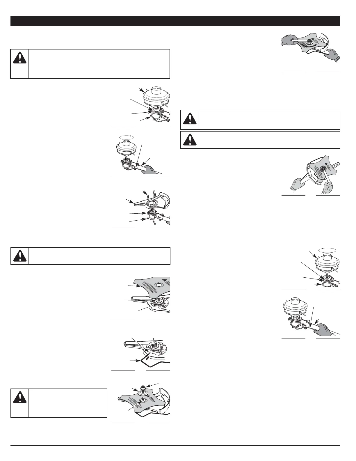
Removing the Brush Cutter Blade
1. Align the shaft bushing hole with the locking
rod slot and insert the locking rod into the
bushing hole (Fig. 8).
2. Hold the locking rod in place by grasping it next
to the shaft housing (Fig. 11).
3. While holding the locking rod, loosen the nut
on the blade by turning it clockwise with a 1/2
inch closed-end or socket wrench (Fig. 11).
4. Remove the nut, blade retainer and blade.
Store the nut and blade together for future use in a secure place. Store
out of children’s reach.
Removing the Brush Blade Guard
1. Loosen and remove the three guard bolts and nuts using a 7/16 inch
closed-end or socket wrench (Fig. 6). Store with brush cutter blade for
future use.
Installing the Cutting Head
1. Position the cutting head as shown (Fig. 12).
Align the shaft bushing hole with the locking
rod slot. Insert the locking rod into the shaft
bushing hole.
2. Hold the locking rod in place by grasping it
next to the boom of the shaft housing (Fig 13).
3. While holding the locking rod, attach the
cutting head to the output shaft by screwing it
counterclockwise until it is fully seated (Fig. 12).
Installing the Cutting Head Shield
Refer to Installing the Cutting Head Shield in the
Trimmer Assembly section.
5
ASSEMBLY INSTRUCTIONS
BRUSH CUTTER ASSEMBLY
Removing the Cutting Head
If you want to trim or remove thicker, tougher
and thornier brush, you must use the metal
brush cutter blade. This is supplied with its own
blade guard which must be securely attached to
the trimmer head. In order to do this, both the
cutting head and cutting head shield must first
be removed from the trimmer unit. To safely
attach the brush cutter to the unit, follow these
instructions:
1. Remove the cutting head shield from the
shaft housing (Fig. 3).
2. Position the cutting head as shown (Fig. 4).
Align the shaft bushing hole with the locking
rod slot. Insert the locking rod into the shaft
bushing hole.
3. Hold the locking rod in place by grasping it
next to the boom of the shaft housing (Fig 5).
4. While holding the locking rod, remove the
cutting head attachment by unscrewing it
clockwise (Fig. 5). Store the cutting head for
future use.
Installing the Brush Blade Guard
1. Place the brush blade guard onto the
trimmer head with the three holes aligned.
2. Attach the blade guard to the trimmer head
with the three guard bolts and nuts using a
7/16 inch closed-end or socket wrench (Fig. 6).
Installing the Brush Cutter Blade
1. Place the cutting blade on the output shaft bushing (Fig. 7).
2. Make sure that the cutting blade is centered
on the pilot step and sitting flat against the
output shaft bushing (Fig. 9).
3. Align the shaft bushing hole with the locking
rod slot and insert the locking rod into the
bushing hole (Fig. 8).
4. Put the blade retainer and nut on the output
shaft. Make sure that the blade is installed
correctly.
5. Tighten nut counterclockwise against the
blade while holding the locking rod:
• If using a torque wrench and an 1/2 inch
socket tighten to: 325 - 335 in•lb, 27 - 28
ft.•lb, 37 - 38 N•m.
• Without a torque wrench, use a 1/2 inch
closed-end or socket wrench, turning the
nut until the blade retainer is snug against
the shaft bushing. Make sure that the
blade is installed correctly, then rotate the
nut an additional 1/4 to 1/2 turn
counterclockwise (Fig. 10).
6. Remove the locking rod from the locking rod
slot.
WARNING: Before using the brush cutter attachment, make
sure that only the metal blade guard is attached to the trimmer
head. Always make sure to remove the plastic cutting guard shield
when using the brush cutter attachment. Failure to do so may
cause serious personal injury or damage to the unit.
WARNING: If the cutting blade is off-center, the unit will vibrate
and the blade may fly off, causing possible serious personal injury.
WARNING: To avoid serious
personal injury or damage to the
unit, do not start or operate this unit
with the locking rod in the locking
rod slot.
WARNING: Do not sharpen the cutting blade. Sharpening the
blade can cause the blade tip to break off while in use. This can
result in severe personal injury. Replace the blade.
WARNING: To avoid serious personal injury, always wear
gloves while handling or installing the blade.
Fig. 7
Pilot
Step
Output Shaft
Bushing
Cutting
Blade
Fig. 4
Shaft
Bushing
Hole
Locking Rod
Cutting Head
Fig. 5
Shaft
Housing
Locking
Rod
Fig. 8
Locking
Rod
Shaft Bushing
Hole
Locking
Rod Slot
Fig. 9
Output
Shaft
Nut
Blade
Retainer
Fig. 10
1/4-1/2 Turn
Counterclockwise
Fig. 6
Trimmer
Head
Guard Bolts (3)
Brush
Blade
Guard
Fig. 11
Clockwise
Fig. 12
Fig. 13
Shaft
Housing
Locking
Rod
Locking
Rod Slot
Nuts (3)
Shaft
Bushing
Hole
Locking Rod
Cutting Head
Locking
Rod Slot
 Loading...