6
ASSEMBLY INSTRUCTIONS
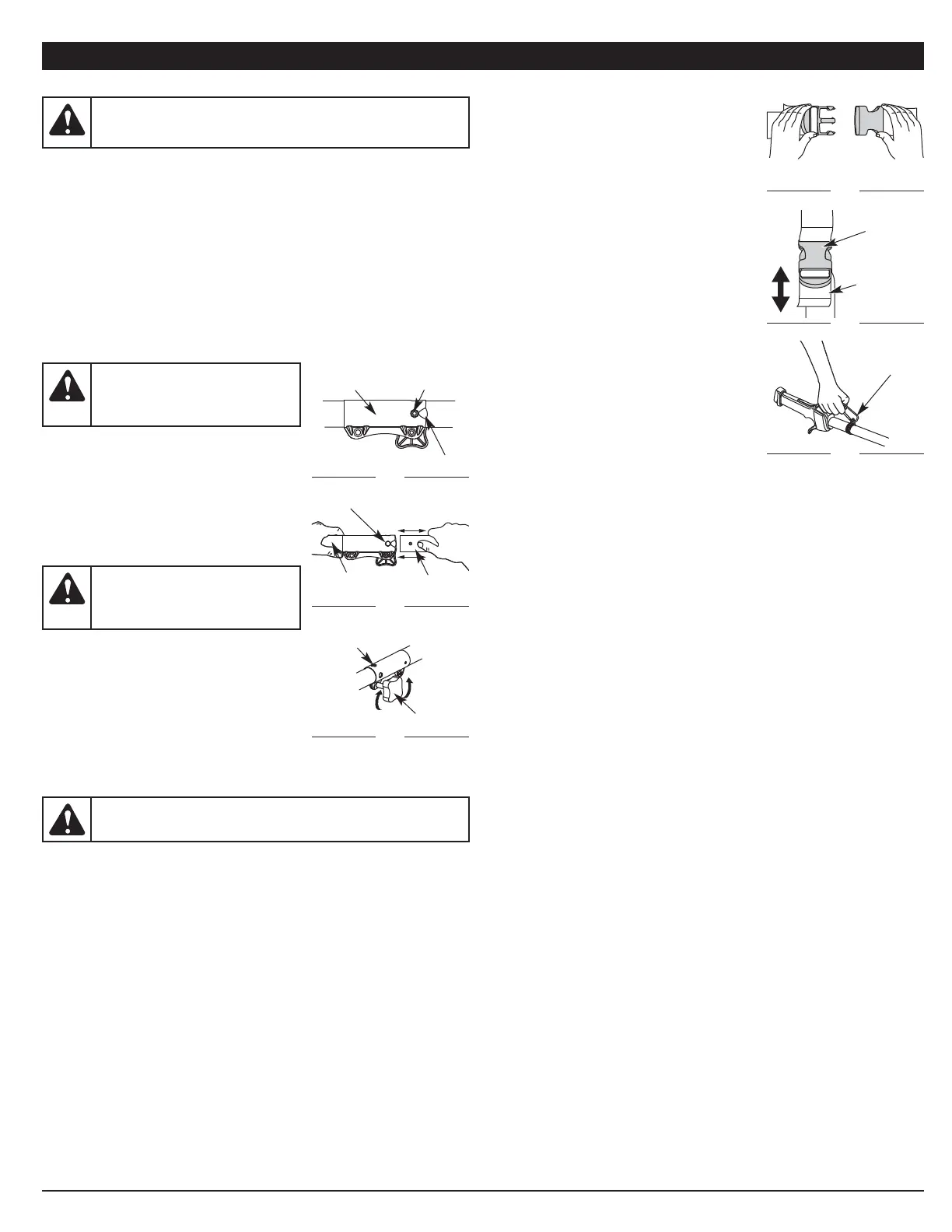
INSTALL THE SHOULDER SUPPORT
1. Put the shoulder support on using the clip.
(Fig. 17).
2. Adjust by lifting slightly on the rear of the
lower clip then push or pull the loose end of
the strap length to fit the operator’s size and
comfort (Fig. 18).
3. Attach the shoulder clip to the unit (Fig. 19).
Fig. 17
Fig. 18
Adjustment
Tab
Support
Clip
Fig. 19
Support
Fitting
OPERATING THE RAPID-LINK™ SYSTEM
The Rapid-Link™ system enables the use of these optional Add-Ons:
Trimmer. . . . . . . . . . . . . . . . . . . . . . . . . . . . . . . . . . . . . . . . . . . . . . . . . AF720
Hedge Trimmer . . . . . . . . . . . . . . . . . . . . . . . . . . . . . . . . . . . . . . . . . . AH720
Brushcutter . . . . . . . . . . . . . . . . . . . . . . . . . . . . . . . . . . . . . . . . . . . . . BC720*
Cultivator . . . . . . . . . . . . . . . . . . . . . . . . . . . . . . . . . . . . . . . . . . . . . . GC720
Edger. . . . . . . . . . . . . . . . . . . . . . . . . . . . . . . . . . . . . . . . . . . . . . . . . . . LE720
Pole Saw . . . . . . . . . . . . . . . . . . . . . . . . . . . . . . . . . . . . . . . . . . . . . . . PS720
Straight Shaft Trimmer. . . . . . . . . . . . . . . . . . . . . . . . . . . . . . . . . . . . . SS725
Turbo Blower . . . . . . . . . . . . . . . . . . . . . . . . . . . . . . . . . . . . . . . . . . . . TB720
*Do NOT use this attachment with an electric powered unit.
Removing the Cutting Attachment or Add-On
1. Turn the knob counterclockwise to loosen
(Fig. 16).
2. Press and hold the release button (Fig. 14).
3. While firmly holding the upper shaft housing,
pull the cutting attachment or add-on straight
out of the Rapid-Link™ coupler (Fig. 15).
Installing the Cutting Attachment or Add-On
NOTE: Place the unit on the ground or on a
work bench to make add-on
installation or removal easier.
1. Turn knob counterclockwise to loosen (Fig. 16).
2. While firmly holding the add-on, push it straight
into the Rapid-Link™ coupler (Fig. 15).
NOTE: Aligning the release button with the
guide recess will help installation
(Fig. 14).
3. Turn the knob clockwise to tighten (Fig. 16).
For edging (when using the line head cutting attachment with Rapid-Link™
models), lock the release button of the cutting attachment into the 90°
edging hole (Fig. 16).
WARNING: Before you begin using any attachment, read and
understand the manual that came with the attachment. Follow all
safety information contained within.
WARNING: To avoid serious
personal injury and damage to the
unit, shut the unit off before
removing or installing add-ons.
CAUTION: Lock the release button in the primary hole and
securely tighten the knob before operating this unit.
CAUTION: Add-ons are to be
used in the primary hole only. Using
the wrong hole could lead to
personal injury or damage to the unit.
Guide Recess
Fig. 14
Release
Button
Rapid-Link™
Coupler
Upper Shaft
Housing
Fig. 15
Lower Shaft
Housing
Primary Hole
Knob
Fig. 16
90˚ Edging Hole
(Trimmer Only)
 Loading...