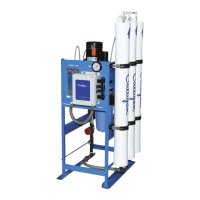
10 Culligan® Series E2 Plus Reverse Osmosis
10 Cat. No. 01023094
Operation
CP Controller Board
The CP controller board controls the Culligan E1, M1, and E2 commercial RO product lines. This board requires no pro-
gramming and has the following capabilities:
• 208-230 VAC single-phase motor up to 1 HP
• Line pressure front side flush prior to startup
• Line pressure front side flush every two hours of continuous make water
• Shut-down upon loss of inlet water pressure and auto-restart
• Power-loss and return auto-restart
• Pretreatment lockout
• Storage tank level (or pressure) switch control
• Diagnostic indicator lights and “Run Now” button
The CP controller is designed for simple control of small RO systems with the following characteristics:
• Inlet pressure switch to detect the presence/absence of feed water pressure to the RO
• Inlet solenoid valve, which is normally closed when the RO is off. The valve opens just prior to startup, remaining
open as long as the RO is in a make-water mode
Controller Behavior when Power First Applied
1. When main power is first applied to the CP controller, the controller will first wait for a one-hour delay. To imme-
diately start the system, press the red “Run Now” button on the bottom of the controller. The “Run Now” button
will not work if any of the five events in step 5 are occuring.
2. The controller will then open the RO inlet solenoid valve, waiting for an additional one-minute period. During this
period, feed water under line pressure enters the RO, psses through the pump, flushes through the upstream
(feed water side) of the membranes, and then passes to the drain.
3. Because the line pressure is expected to be fairly low (less than 100 psi) very little permeate water is created
during this flush time. Instead, any high-TDS water on the membrane feed side is flushed to drain.
4. When the one-minute period has elapsed, the controller checks to see if there is sufficient incoming water pres-
sure to operate the RO.
a. If there IS pressure, the controller turns on the main pump and the RO begins to produce permeate
water.
b. If there is NOT sufficient pressure, the entire process starts over, beginning with the one-hour delay.
c. As long as there is applied power and water pressure is being supplied to the unit, the RO will repeat
this delay, flush, and attempt to start cycle indefinitely up to 24 restart attempts per day.
5. Once the controller successfully enters the make-water mode, it will continue to operate the pump and produce
RO water until one of the following five events occurs:
• Tank Full switch indication
• Pretreatment lockout indication
• Loss of electrical power
• Loss of inlet pressure
• Two-hour continuous make-water timer expiration
When any of these five events occurs the system immediately ceases making RO water. The pump will turn off
and close the inlet solenoid.
6. If the unit has stopped for either tank full or pretreatment lockout conditions, it will remain off until these condi-
tions no longer exist. The unit will then reopen the inlet solenoid, wait one minute, and then start the pump to
return to the make-water condition.
7. If the unit has stopped because of either an electrical power loss or loss of inlet pressure, the system will follow
the behavior described in step 1.
8. If the unit stops because it has been in a continuous make-water operation for the previous two hours, the pump
will remain off for one minute. During the time, the inlet solenoid valve will remain open, and the system will
perform a line-pressure front-side membrane flush to drain. At the end of the minute, the system will return to
make-water mode.
 Loading...