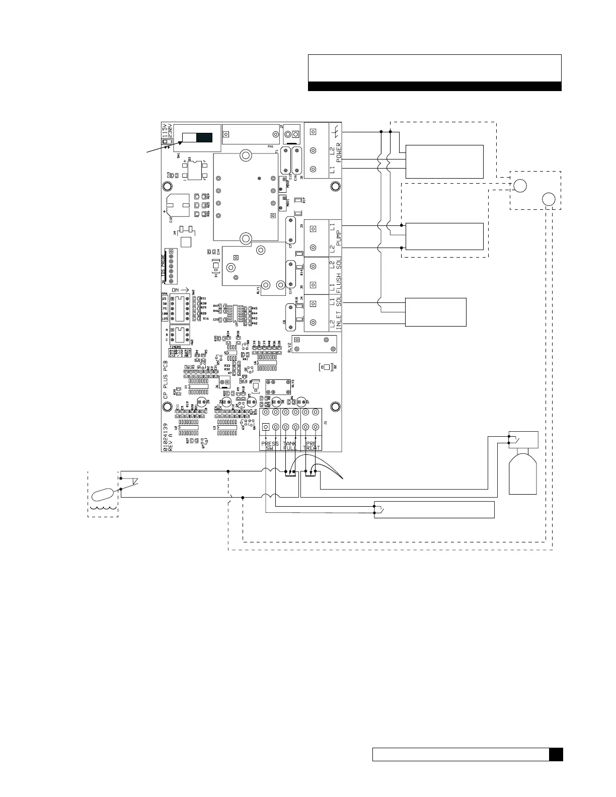
Wiring Diagram 27
Cat. No. 01023094
Wiring Diagram
Series E2 Plus Wiring Diagram
115/230
VOLTAGE
SELECTOR
CABLE, SOLENOID
BLACK
RED
POWER CORD, MOTOR
WHITE
BLACK
BLACK
WHITE
115V/230V,
60Hz/50Hz,1PH
INCOMING POWER
CABLE, INLET PRESSURE SWITCH
WHITE
RED
LEVEL CONTROL INPUT AND
PRETREATMENT LOCKOUT INPUT
(Remove jumpers when installing TANK FULL
Switch or Pretreatment Lockout Connection)
GREEN
GREEN
GREEN
NOTE: The inlet pressure switch is CLOSED when the
pressure is sufficient for the RO to run.
NORMALLY CLOSED Level
The switch
is CLOSED when water level
is below the float or pressure
in the storage tank is below
the shutof
f pressure.
STORAGE TANK
PRETREATMENT LOCKOUT SWITCH
A NORMALLY CLOSED switch is required. This
switch is OPEN during regeneration, but is
CLOSED at all other times.
SV4
PS
PRESSURIZED
STORAGE KIT
D1013880
B:LACK
GREEN
WHITE
RED
Figure 10. Series wiring diagram.
 Loading...