xStack® DGS-3420 Series Layer 2+ Managed Stackable Gigabit Switch Hardware Installation Reference Guide
23
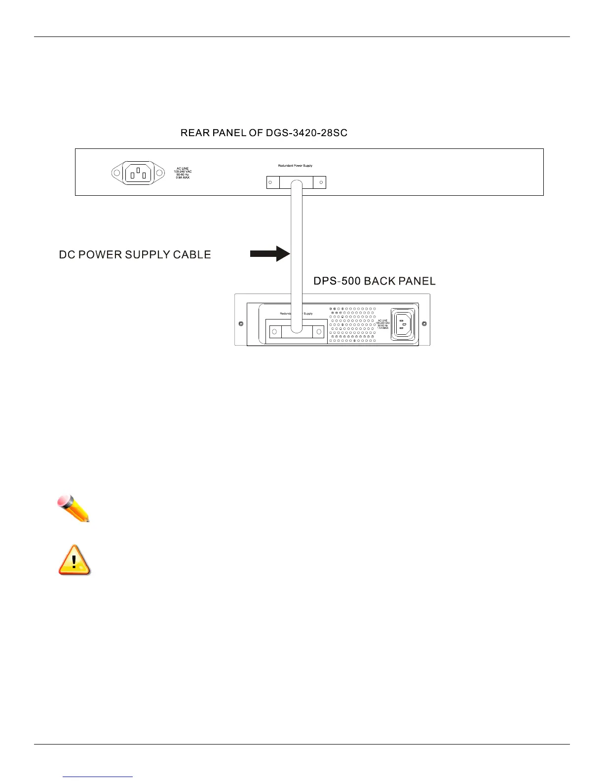
Connecting to a Redundant Power Supply
The Switch connects to the Master Switch using a 14-pin DC power cable. A standard, three-pronged AC power cable
connects the redundant power supply to the main power source.
Figure 2–6 Connecting a DGS-3420 Series Switch to the DPS-500 (28TC, 28SC, 26SC, and 52T)
1. Insert one end of the 14-pin DC power cable into the port on the switch and the other end into the redundant
power supply.
2. Using a standard AC power cable, connect the redundant power supply to the main AC power source. A green
LED on the front of the DPS-500 will glow to indicate a successful connection.
3. Re-connect the switch to the AC power source. The LED indicator will show that a redundant power supply is now
in operation.
4. Do not make any changes on the switch.
NOTE: See the DPS-500 documentation for more information.
CAUTION: Only the DGS-3420-28TC, DGS-3420-28SC, DGS-3420-26SC, and the DGS-3420-52T
use the DPS-500. The DGS-3420-28PC and the DGS-3420-52P use the DPS-700.
 Loading...