67
8 - PARTICULAR INSTALLATIONS
8.1 - Inhibiting self-priming
The product is made and supplied with the capacity of being self-priming.
With reference to par. 4, the system is able to prime and therefore oper-
ate in whatever installation conguration chosen: below head or above
head. However there are cases in which the self-priming capacity is not
necessary, or areas where it is forbidden to use self-priming pumps. Dur-
ing priming the pump obliges part of the water already under pressure
to return to the suction part until a pressure value is reached at delivery
whereby the system can be considered primed. At this point the recirculat-
ing channel closes automatically. This phase is repeated each time the
pump is switched on, even already primed, until the same pressure value
that closes the recirculating channel is reached (about 1 bar).
When the water arrives at the system intake already under pressure (maxi-
mum allowed 2 bar) or when the installation is always below head, it is pos-
sible (and mandatory where local regulations require it) to force the closure
of the recirculating pipe, losing the self-priming capacity. This obtains the
advantage of eliminating the clicking noise of the pipe shutter each time
the system is switched on.
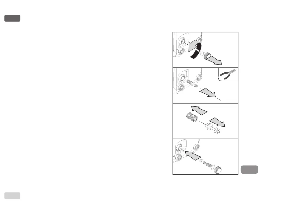
To force closure of the self-priming pipe, proceed as follows:
1. Disconnect the power supply;
2. empty the system (unless you decide to inhibit self-priming at the rst
installation);
3. remove the drainage cap on Face E, taking care not to drop the
O-Ring (Fig.18);
4. with the aid of pliers take the shutter out of its seat. The shutter will be
extracted together with the O-Ring and the metal spring with which
it is assembled;
5. remove the spring from the shutter; insert the shutter in its seat again
with the respective O-Ring (side with gasket towards the inside of the
pump, stem with cross-shaped ns towards the outside);
6. screw on the cap after having positioned the metal spring in side
so that it is compressed between the cap itself and the with cross-
shaped ns of the shutter stem. When repositioning the cap ensure
that the respective O-Ring is always correctly in its seat;
7. ll the pump, connect the power supply, start the system.
Figure 18

 Loading...