Installation and operation manual
15
EWAQ016~064BAW + EWYQ016~064BAW
Packaged air-cooled water chiller
4PW70082-1C – 2013.07
How to connect for multi unit
4.7. Install optional equipment
For the installation of the optional equipment, refer to the installation
manual which is delivered with the optional equipment or the
addenda delivered with this chiller.
5. COMMISSIONING THE CHILLER
5.1. Verify completion of installation
After the installation of the unit, check the following:
1 Field wiring
Make sure that the field wiring has been carried out according to
the instructions described in the chapter "4.6.5. Connection of
the unit power supply and communication cable(s)" on page 13,
according to the wiring diagrams and according to European
and national regulations.
2 Fuses and protection devices
Check that the fuses and other locally installed protection
devices are of the size and type specified in the chapter
"Electrical specifications" on page 24. Make sure that neither a
fuse nor a protection device has been bypassed.
3 Earth wiring
Make sure that the earth wires have been connected properly
and that the earth terminals are tightened.
4 Internal wiring
Visually check the switch box and the inside of the unit on loose
connections or damaged electrical components.
5 Installation
Check that the unit is properly installed, to avoid abnormal
noises and vibrations when starting up the unit.
6 Damaged equipment
Check the inside of the unit on damaged components or
squeezed pipes.
7 Refrigerant leak
Check the inside of the unit on refrigerant leakage. If there is a
refrigerant leak try to repair the leak (recovery, repair, and
vacuuming needed). If it is impossible to repair by yourself, call
your local dealer.
Do not touch any refrigerant which has leaked out of refrigerant
piping connections.
This may result in frostbite.
8 Water leak
Check the inside of the unit on water leakage. In case there is a
water leakage try to repair the leak. If it is impossible to repair by
yourself, close the water inlet and water outlet shut-off valves
and call your local dealer.
9 Power supply voltage
Check the power supply voltage on the local supply panel. The
voltage must correspond to the voltage on the identification label
of the unit.
10 Air purge valve
Make sure the air purge valve of the unit is open (at least
2 turns). Refer to "[E-04] Pump only operation (air purge
function)" on page 21.
11 Shut-off valves
Make sure that the shut-off valves are correctly installed and
fully open.
Once all checks are fulfilled, the unit must be closed, only then can
the unit be powered up. When the power supply to the unit is turned
on, "88" is displayed on the remote controller during its initialization,
which might take up to 30 seconds. During this process the remote
controller can not be operated.
5.2. Configure the unit
5.2.1. Final air purging
To get rid of all the air in the system, the pump should be operated.
Therefore, change the field setting [E-04] as explained in the chapter
"5.2.3. Field settings on the remote controller" on page 17. More
details about setting "[E-04] Pump only operation (air purge function)"
can be found on page 21.
5.2.2. Field setting on outdoor module(s)
If required, carry out field settings according to the following
instructions. Refer to the service manual for more details.
Opening the switch box and handling the switches
When carrying out field settings, remove
the inspection cover (1).
Operate the push buttons with an insulated
stick (such as a ball-point pen) to avoid
touching live parts.
Make sure to re-attach the inspection cover (1) into the switch box
cover (2) after the job is finished.
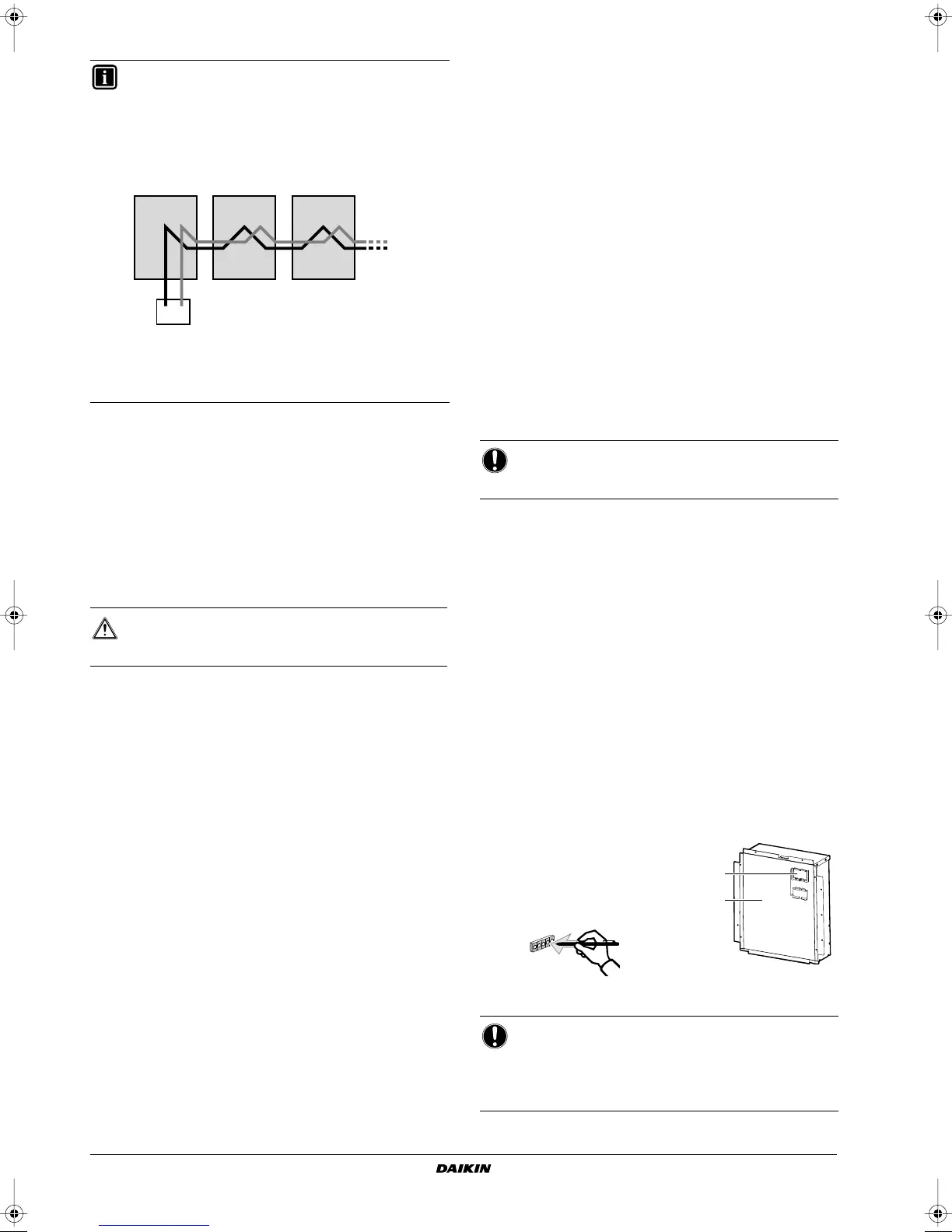
INFORMATION
For multiple unit control, connect the remote controller to
the unit as instructed above. For all other units to be
controlled by this controller every next unit has to be
connected as shown in the figure below (meaning: make a
connection from P1 of the previous unit to P1 of the next
unit, and make a connection from P2 of the previous unit to
P2 of the next unit, and so on...).
Limitation: 16 PCB’s EWA/YQ016~032
counts as 1 PCB
EWA/YQ040~064
counts as 2 PCB’s
WARNING
Switch off the power supply before making any
connections.
P1 P1 P1P2
P1 P2
P2 P2
remote controller
NOTICE
Operating the system with closed valves will damage the
pump!
NOTICE
Make sure that all outside panels, except for the panel on
the electric box, are closed while working.
Close the lid of the electric box firmly before turning on the
power.
2
1
4PWEN70082-1C.book Page 15 Wednesday, September 25, 2013 7:31 AM
 Loading...