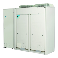
EWAQ016~064BAW + EWYQ016~064BAW
Packaged air-cooled water chiller
4PW70082-1C – 2013.07
Installation and operation manual
4
3.2.1. General precautions on installation location
Select an installation site that meets the following requirements:
■ The foundation must be strong enough to support the weight of
the unit. The floor must be flat to prevent vibrations and noise
generation and to have sufficient stability.
■ The space around the unit is adequate for maintenance and
servicing (refer to "3.4. Service space" on page 4).
■ The space around the unit allows sufficient air circulation.
■ There is no danger of fire due to leakage of inflammable gas.
■ The equipment is not intended for use in a potentially explosive
atmosphere.
■ Select the location of the unit in such a way that the sound
generated by the unit does not disturb anyone, and the location
is selected according the applicable legislation.
■ Take minimum and maximum water volumes and installation
heights into account, refer to "4.5. Perform the water piping
work" on page 10.
■ Take care that in the event of a water leak, water cannot cause
any damage to the installation space and surroundings.
■ Do not install in the following locations.
■ Locations where sulphurous acids and other
corrosive gases may be present in the
atmosphere.
Copper piping and soldered joints may
corrode, causing refrigerant to leak.
■ Locations where a mineral oil mist, spray or
vapour may be present in the atmosphere.
Plastic parts may deteriorate and fall off or
cause water leakage.
■ Locations where equipment that produces
electromagnetic waves is found.
The electromagnetic waves may cause the
control system to malfunction, preventing
normal operation.
■ Locations where flammable gases may leak,
where thinner, gasoline and other volatile
substances are handled, or where carbon
dust and other incendiary substances are
found in the atmosphere.
Leaked gas may accumulate around the unit,
causing an explosion.
■ When installing, take strong winds, typhoons or
earthquakes into account.
Improper installation may result in the unit turning
over.
3.2.2. Weather dependent precautions
■ Select a place where rain can be avoided as much as possible.
■ Be sure that the air inlet of the unit is not positioned towards the
main wind direction. Frontal wind will disturb the operation of the
unit. If necessary, use a screen to block the wind.
■ Ensure that water cannot cause any damage to the location by
adding water drains to the foundation and prevent water traps in
the construction.
■ Do not install the unit in areas where the air contains high levels
of salt such as that near the ocean.
3.2.3. Selecting a location in cold climates
■ To prevent exposure to wind and snow, install a baffle plate on
the air side of the outdoor unit:
■ In heavy snowfall areas it is very important to select an
installation site where the snow will not affect the unit. If lateral
snowfall is possible, make sure that the heat exchanger coil is
not affected by the snow (if necessary construct a lateral
canopy). Refer to figure 1.
1 Construct a lateral canopy.
Make sure that the air blowing out of the unit is not
obstructed.
2 Baffle plate
3 Construct a pedestal.
Install the unit high enough off the ground to prevent
burying in snow.
3.3. Dimensions of outdoor unit
Refer to figure 6.
1 Pitch of foundation bolt holes
(15x22.5 oblong holes)
3.4. Service space
The space around the unit is adequate for servicing and the minimum
space for air inlet and air outlet is available. (Refer to the figure below
and choose one of the possibilities). Refer to figure 2.
1 Distance from wall (or other unit) in regions without heavy
snowfall
2 Distance from wall (or other unit) in regions with heavy
snowfall
Suction side
The installation space required on this drawing is for full load heating
operation without considering possible ice accumulation.
If the location of the installation is in a region with heavy snowfall,
then dimensions a and b should be >500 mm to avoid accumulation
of ice in between the units.
3.5. Prepare the water piping work
The units have a water inlet and water outlet for connection to a water
circuit. This circuit must be provided by a licensed technician and
must comply with all applicable legislations.
Before continuing the installation of the unit, beware of the following
points:
■ Two shut-off valves are delivered with the unit. To facilitate
service and maintenance, install as shown in "4.5.2. Installing
the shut-off valve kit" on page 10.
■ Drain taps must be provided at all low points of the system to
permit complete drainage of the circuit. A drain valve is provided
inside the unit.
■ Air purges must be provided at all high points of the system. The
vents should be located at points which are easily accessible for
servicing. An automatic air purge is provided inside the unit.
Check that this air purge valve is not tightened too much so that
automatic release of air in the water circuit remains possible.
Refer to the "[E-04] Pump only operation (air purge function)" on
page 21.
INFORMATION
When operating the unit in a low outdoor ambient
temperature, be sure to follow the instructions described
below.
NOTICE
The unit is only to be used in a closed water system.
Application in an open water circuit can lead to excessive
corrosion of the water piping.
4PWEN70082-1C.book Page 4 Wednesday, September 25, 2013 7:31 AM
 Loading...