www.DaikinApplied.com 11 IM 1285-4 • MICROTECH III
Power must NOT be applied to the MT III or other devices when wiring to
the controller.
After all of the sensors, switches, relays, actuators, controllers
and modules are installed, the wiring to the MicroTech III can
begin. A full wiring diagram can be found in Appendix B on
page 19. 20 AWG 600 V rated wire is recommended. Use
the wire raceways around the edges of the control panel to
ensure neatness and terminate wires on the MicroTech III
correctly. Landing a voltage wire on the wrong controller could
blow the internal MT III fuse.
Terminal Blocks
Table 3 on page 8 shows, terminal blocks TB1A, TB1B,
TB2A, TB2B and TBG are each designated for a specic
voltage potential. Mechanical jumpers must be installed across
each of the terminal blocks in order to create an equal potential
through the block. The individual TBG terminal block pieces will
be grounded to the unit’s case through the DIN rail. TB1B and
TB2B need to receive their potential from TBG and then jump
across the terminal blocks. See diagram in Figure 15.
Transformers
The secondary’s of the T1 and T2 transformers each consist
of a positive (+) and a common potential. Table 3 shows each
terminal block is designated for a specic potential. Follow the
diagram below in Figure 15 and the schematic in Appendix B
when wiring the transformers
The MT III MCB is powered by 24 VAC from T2. On the MCB,
wire T1-G to TB2A-101 and T1-G0 to TB2B-101.
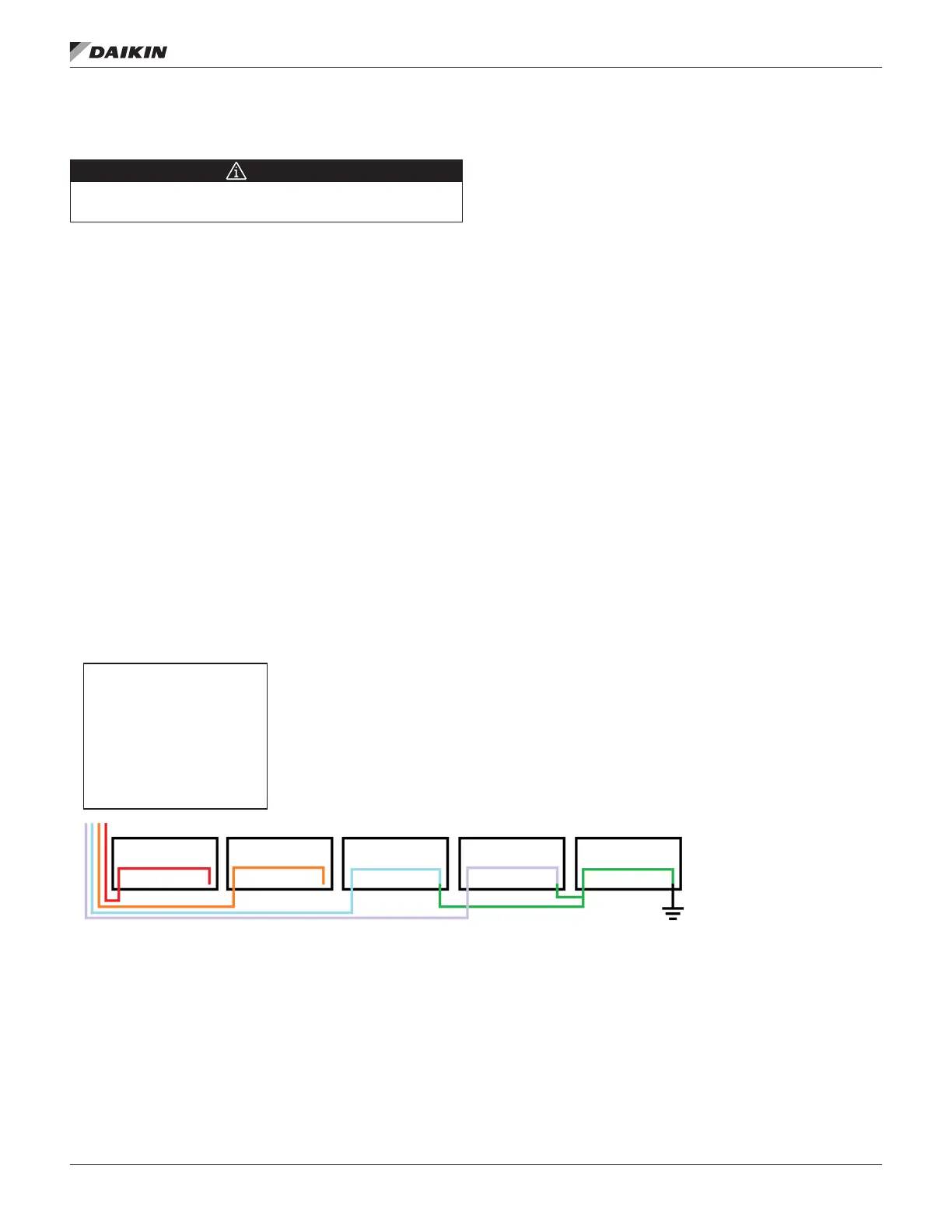
Figure 15: Typical Transformer Schematic
Purple: 24 VAC Common
Red: 120 VAC +
Blue: 120 VAC Common
Note: Each of the separate terminal blocks shown above need to have an equal voltage
across all of the terminals. The colored lines show what voltage should exist on each block.
TB1A should have 120 VAC + on each terminal on the block and TB1B should have 24 VAC
+ on each terminal on the block. TB1B and TB2B are “common” and share the voltage from
the TBG (ground); this voltage is then jumped through the blocks. The TBG block is
grounded through the DIN rail to the case. TB3 (not shown here) will not have the same
voltage across all the terminals and jumpers are not needed.

 Loading...


