IM 1285-4 • MICROTECH III 4 www.DaikinApplied.com
Table 2: Additional Parts Necessary
Label Maker
20 AWG 600 V wire
Spade Connectors
Network Communication Card
• Choose a Network Communication Card from the list
below if necessary. A 10 pin connector will also be
necessary with a Communication Card.
• The communication card is not included in the kit and
must be ordered separately
BACnet MSTP 90016710
BACnet Lon CAV 90016711
BACnet IP 90016709
BAC LonVAV 90016712
10 pin connector 300047027
BACnet MSTP 90016710
BACnet Lon CAV 90016711
BACnet IP 90016709
BAC LonVAV 90016712
10 pin connector 300047027
The purpose of this instruction manual is to guide a
technician through the process of converting a MicroTech I
Controller (MT I) to a MicroTech III Controller (MT III) on a
Self-Contained unit. The MT III controller has an advanced
navigation structure, improved metrics, trending data
capability and network compatibility. Each Self-Contained
unit will have small dierences, such as the number of
compressors or a VFD for the supply fan. Recognizing these
dierences and following the instructions throughout the
manual will ensure a successful conversion.
Follow all Lock-Out Tag-Out procedures to minimize risks of injury during
this procedure. Always use proper rigging and lifting procedures! Always
wear appropriate levels of PPE governed by the hazards which are present.
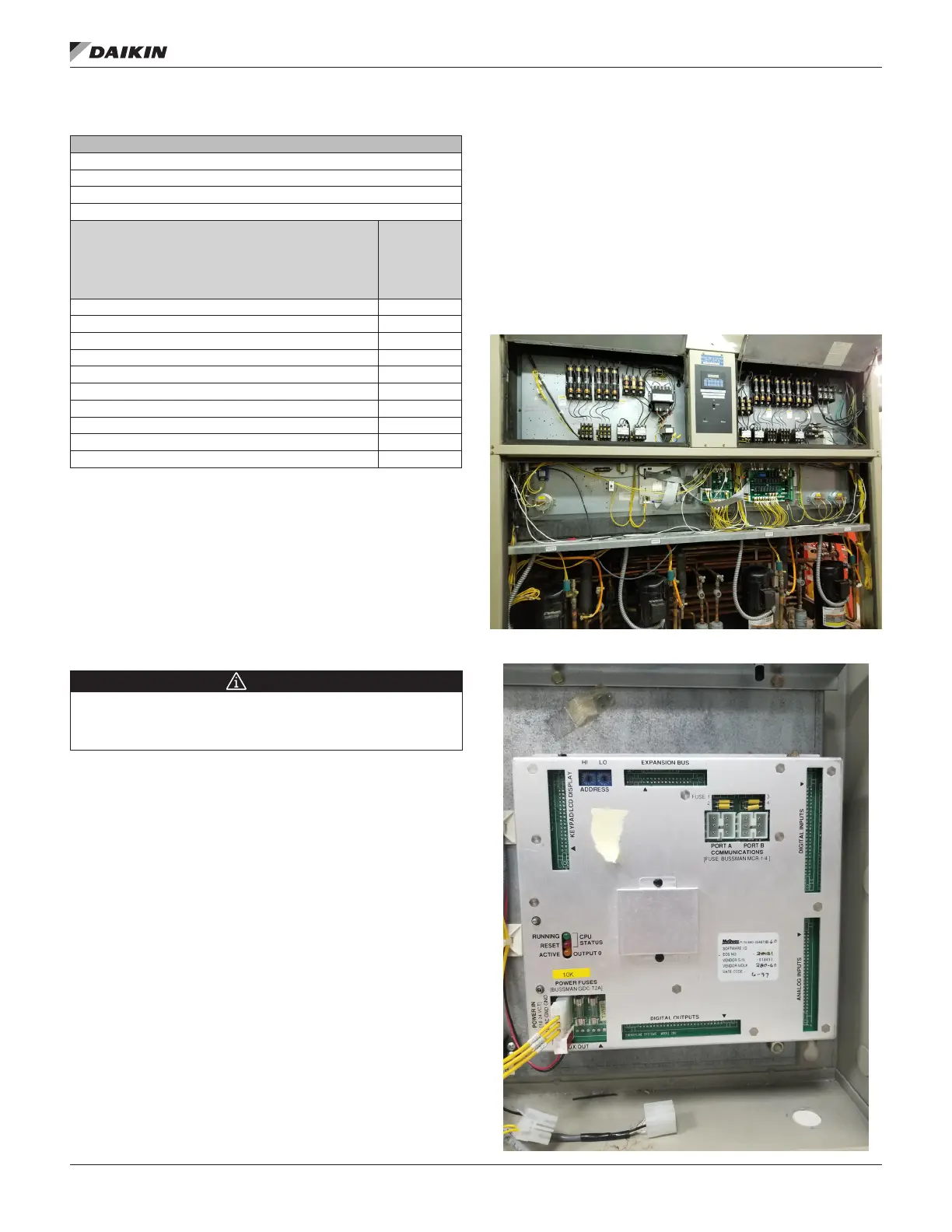
Figure 1 shows a typical control panel layout before the
conversion begins. Look for three electrical control boards
mounted to the control panel: Main Control Board (MCB),
Output Board, and Input Board (See Figure 2, Figure 3, and
Figure 4). Before removing the three boards, each of the
wires connected to the boards must be labeled with a label
maker. Labeling the wires will allow the technician to be more
organized and rewire the control panel correctly once the
MicroTech III is installed.
Figure 1: Typical Control Panel Layout
Figure 2: Main Control Board (MCB)

 Loading...


