IM 1285-4 • MICROTECH III 16 www.DaikinApplied.com
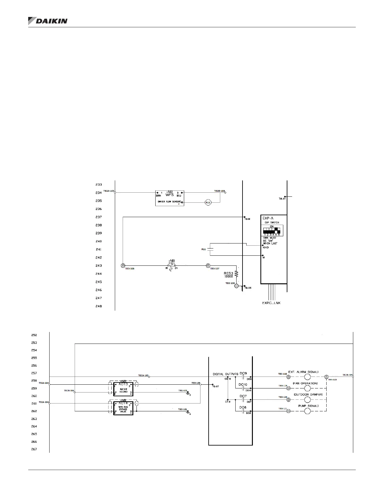
The Freezestat (FS1) is a temperature-based switch that is
designed to open at low temperatures in order to protect the
coil. The Freezestat should be wired in series with a 1 kΩ
resistor. When the Freezestat opens the circuit between X5
and M on the MT III MCB, the unit will read an open signal and
alarm. See Figure 21.
The water ow sensor is powered by 24 VAC from transformer
T2. Relay R11 closes a set of NO contacts on X5 on Expansion
Module C when the water ow sensor detects water ow. See
Figure 21.
If there is no Water Flow Sensor on the unit, a jumper
needs to be wired between X5 and M on the EXP-A
to avoid nuisance alarms.
The Waterside Economizer valve actuator (ACT3) and Water
Regulator/Bypass valve actuator (ACT4) will be supplied
24+ VAC and 24 VAC Common from the respective terminal
blocks. Land the 2-10 VDC input signal T9-X7 on the MT III
and to terminal 3 on the actuators. These will also need to be
grounded. See Figure 22 for proper wiring.
Figure 21: Expansion Module C
Figure 22: Water Regulator and Bypass Valves

 Loading...


