www.DaikinApplied.com 17 IM 1285-4 • MICROTECH III
A VFD on the Supply Fan motor is required if the unit is
designed for a Variable Air Volume application. The MT III and
VFD communicate drive status and speed through Modbus.
The jumpers shown on VFD are necessary. See an example of
the ABB VFD wiring diagram in Figure 23. Wiring for Schneider
and Danfoss VFDs can be found in Appendix G. Refer to
manual OM 844 and OM 1190 for information on Schneider
and ABB VFDs, respectively.
Once the VFD is installed and wired correctly,
the parameters for the VFD must be set. See
“Programming the VFD” on page 17 in this manual
for instructions.
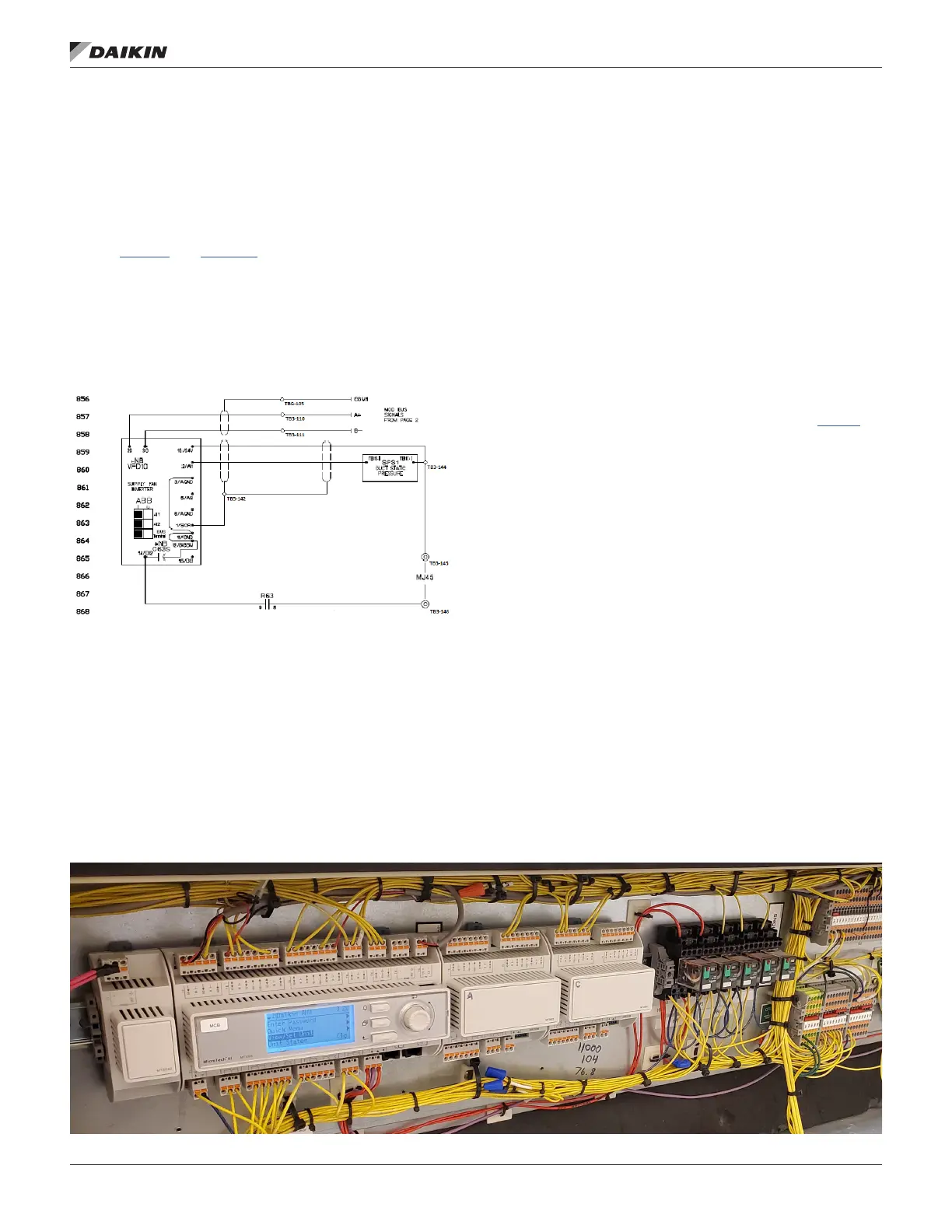
Figure 23: VFD Wiring Diagram
If there is an ABB, Schneider or Danfoss VFD installed, the
Duct Static Pressure sensor wires directly to the VFD. The
4-20mA output signal from the DSP sensor is wired to the AI1
terminal on the ABB VFD. The MT III reads in the DSP sensor
signal through Modbus and sends a speed signal to the VFD
in order to maintain the DSP set point. See Figure 23. See
Appendix G on page 40 for DSP wiring on Schenider and
Danfoss VFDs.
Once the MT III and all of the auxiliary electrical devices are
installed and wired, the controller will need to be programmed.
There are three tasks when programming the MT III controller:
Verify and Update Software Code, Set Unit Conguration, and
Set Parameters.
Verify and Update Software Code
The unit’s software code must be updated to the newest code.
See the SIL in Appendix C on page 23 for instructions on
how to upload code to the MT III controller.
Set Unit Conguration
Each MT III has a unique Unit Conguration that must be set
according to the unit’s features and capabilities. See IM 919 for
instructions and unit conguration options.
Set Parameters
After the software code is updated and the unit conguration is
set, the parameters on the MT III will need to be set.
After the VFD is installed and wired, the parameters need to be
set. See charts in Appendix D through Appendix F and set the
parameters depending on the type of drive.
Figure 24 shows a sample control panel after the conversion
is complete. Be aware that the image below does not include
the white wire organizers or standard terminal blocks used in
this manual. The image should be used as a reference. The
nal product will vary slightly depending on the technician and
job site.
Figure 24: Completed Conversion

 Loading...


