IM 1285-4 • MICROTECH III 6 www.DaikinApplied.com
Once each of the wires is labeled, unplug all wires from MCB,
Output Board, and Input Board. Leave all paired wires in their
respective plugs to keep them organized. Unscrew each of
the boards from the control panel. Remove the wires from the
back of the MT I Display. Unscrew the display and remove from
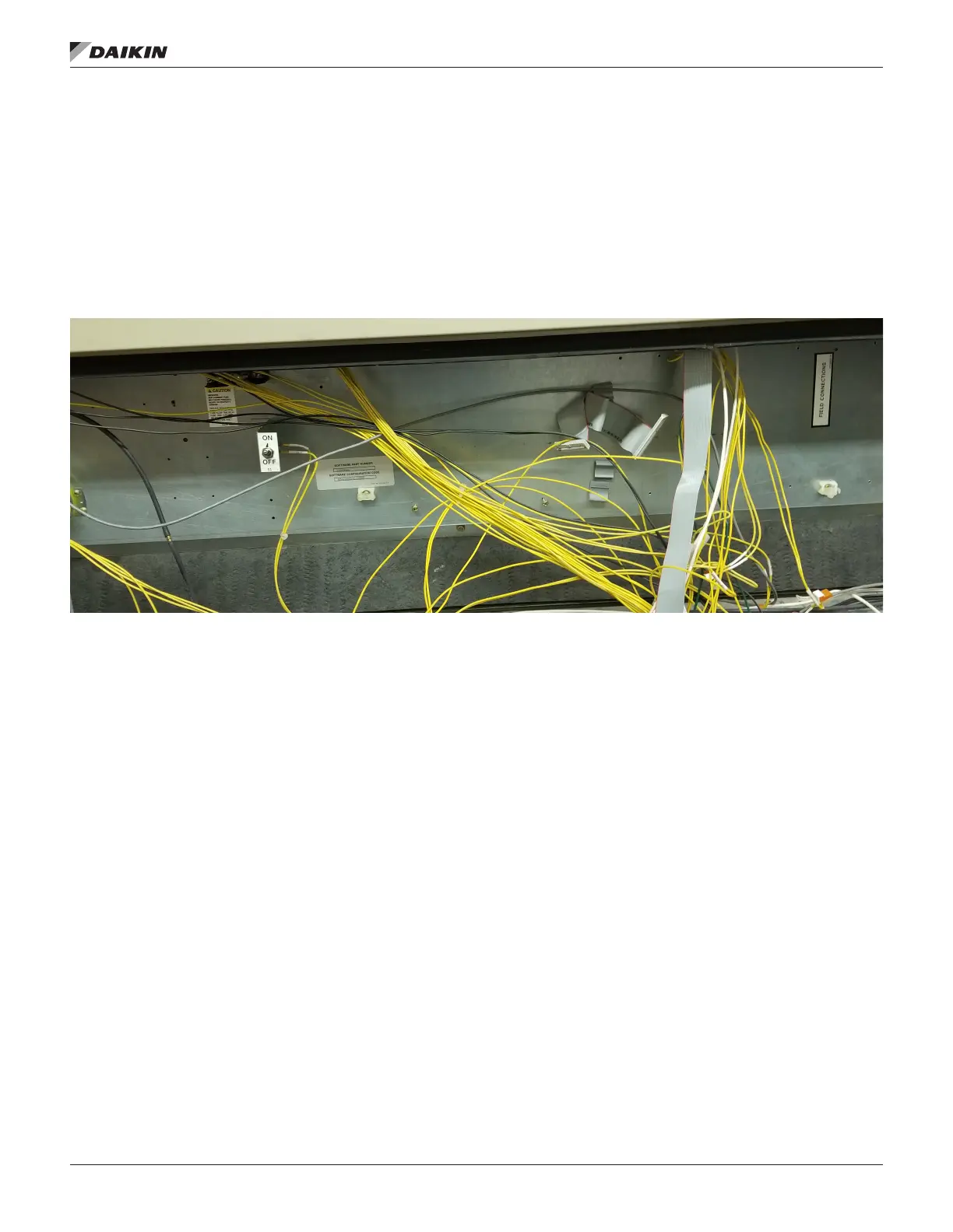
control panel. Figure 5 below shows the control panel with all
wiring labeled and boards removed.
Figure 5: Control Panel without Components
The following temperature sensors will need to be removed
from the unit: DAT, RAT, MAT, EWT. Be aware and take note of
the mounting location for each of these sensors because new
sensors will be remounted and wired to the MT III MCB later on
in this manual.
If the PC5, PC7 and DHL tubing does not need replacing, then
save existing tubing. Be aware and take note of the high and
low side of pressure designations to avoid erroneous readings
after install.

 Loading...


