IM 972-2 • MAVERICK I ROOFTOP SYSTEMS 14 www.DaikinApplied.com
Wiring
Power Supply
DANGER
Power supply to the unit must be disconnected before making eld
connections. To avoid electrical shock, personal injury or death, be sure to
rigorously adhere to eld wiring procedures regarding proper lockout and
tagout of components.
1. All wiring should be made in accordance with the
National Electrical Code. Consult the local power
company to determine the availability of sucient power
to operate the unit. Check the voltage at power supply to
make sure it corresponds to the unit’s RATED VOLTAGE
REQUIREMENT. Install a branch circuit disconnect near
the rooftop, in accordance with the N.E.C., C.E.C. or
local codes.
2. It is important that proper electrical power is available at
the unit. Voltage should not vary more than 10% from
that stamped on the unit nameplate. On three phase
units, phases must be balanced within 3%.
3. For branch circuit wiring (main power supply to unit
disconnect), the minimum wire size for the length of
run can be determined from Table 4 using the circuit
ampacity found on the unit rating plate. Use the smallest
wire size allowable from the unit disconnect to the unit.
Wire size based on 75°C rated wire insulation for 1%
voltage drop.
4. For more than 3 conductors in a raceway or cable, see
the N.E.C. (C.E.C. in Canada) for derating the ampacity
of each conductor.
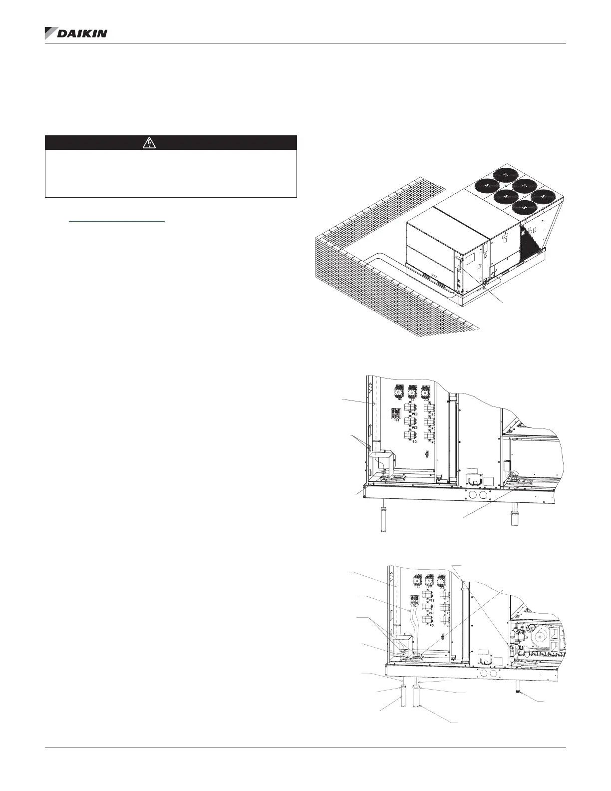
5. For through-the-base wiring entry, reference Figure
15. All ttings and conduit are eld-supplied for this
application. Reference Table 5 for proper hole and
conduit size.
IMPORTANT: This unit is approved for use with copper
conductors only connected to unit contactor. Warranty will be
voided if aluminum wire is connected to unit contactor.
Figure 13: Recommended Branch Circuit Disconnect
Location
Figure 14: Base Entry Locations (Cooling Only)
Figure 15: Base Entry Locations (Gas Heat)
DISCONNECT
RUN THERMOSTAT
WIRINGIN THIS
CHASETO
CONTROL
BOARD
(2) CAP PLUGS
BASE
CONTROL
ENTRY
BASE
POWER
ENTRY
POWERWIRES
FROM DISCONNECT
TO TERMINAL BLOCK
WASHERS
CONTROL VOLTAGE
KNOCKOUT
WIRE FROM
ZONE THERMOSTAT
STRAIGHT CONDUIT
FITTING
CONDUITFRO M
ZONE THERMOSTAT
CONDUIT FROM
POWER SUPPLY
SIZED PERCHART
STRAIGHTCONDUIT
FITTING SIZED
PERCHART
WIRE SIZE FROM
MIN. CIRCUITAMPACITY
CUT HOLE
SIZED PER CHART
OR USEKNOCK OUT
GASLINE
EXTERNALMANUALGAS
SHUT-OFF VALVE
RUNTHERMOSTAT
WIRING IN THIS
TO CONTROL
BOARD
 Loading...