IM 972-2 • MAVERICK I ROOFTOP SYSTEMS 16 www.DaikinApplied.com
Customer Supplied Thermostat
The customer supplied room thermostat must be compatible
with the spark ignition control on the unit. Generally, all
thermostats that are not of the “current robbing” type are
compatible with the integrated furnace control. The low voltage
wiring should be sized as shown in Table 6.
Install the room thermostat in accordance with the instruction
sheet packed in the box with the thermostat.
Figure 17 on page 17 for an example of a typical customer
supplied wiring diagram.
Table 6: Field Wire Size for 24 Volt Thermostat
Solid Copper Wire, AWG
Thermostat
Load Amps
3.0 16 14 12 10 10 10
2.5 16 14 12 12 10 10
2.0 18 16 14 12 12 10
Length of Run – Feet (1)
50 100 150 200 250 300
NOTE: (1) The total wire length is the distance from the furnace to the
thermostat and back to the furnace. DO NOT USE CONTROL WIRING
SMALLER THAN NO. 18 AWG.
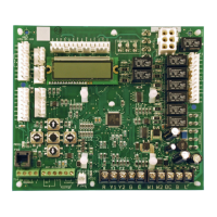
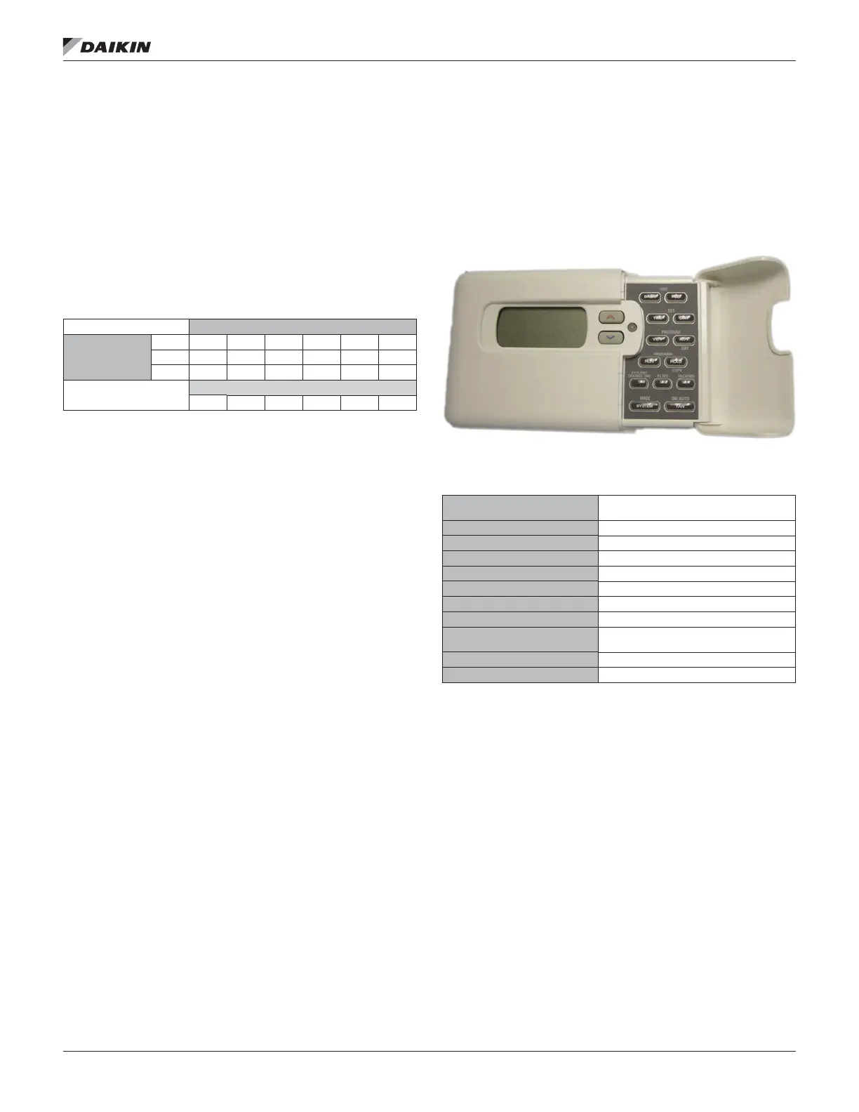
Optional Factory Supplied Thermostat
The optional factory supplied T-170 commercial setback digital
thermostat (Figure 16) uses microcomputer technology to
provide precise time and temperature control. This thermostat
oers the exibility to design heating and cooling programs that
t building needs (refer to Table 7). Figure 18 for an optional
factory supplied thermostat wiring diagram.
Figure 16: Optional T-170 Thermostat
Table 7: Optional Factory Supplied Thermostat
Specications
Electrical Rating Single Stage:
mV to 30 V (ac), NEC Class II, 50/60 Hz
or DC
Electrical Rating Staging: 20 to 30 V (ac), NEC Class II
Terminal Load: 5 A per terminal, 2.5 A max. combined
Setpoint Range: 45° to 99°F (7° to 37°C)
Anticipation, Heating: Adjustable
Anticipation, Cooling: Adjustable
Heat 0.5° to .5°F, Cool 0.8° to 2.2°F
Heat 0.5° to .5°F, Cool 0.5° to 2.2°F
Operating Ambient:
32° to +0°F (0° to +43°C) Operating
Humidity 90% non-condensing max.
Shipping Temperature Range: -4° to 50°F (-20° to 65°C)
Dimensions (H × W × D): 4-1/8" × 6-7/8" × 1-3/8"
 Loading...