Electrical Data
Power Wiring
Table 6: RCS 06G – 20F Electrical Data
Model
RCS
06G 07G 10G 12F 15F 20F
Compressor Motor
Voltage 208/230 460- 208/230 460 208/230 460 208/230 460 575 208/230 460 575 208/230 460 575
Phase and hertz 3 – 60
Number of
compressors
1 2
Operating Current
Rated load amps
(each)
1
25 11.8 27.9 13.6 32.6 14.8 22 .4 10 .6 7 .7 25 .0 12 .2 9 .0 33 .3 17 .9 12 .8
Locked rotor amps
(each)1
149 83 164 100 225 240 130 75 54 164 100 78 239 125 80
Condenser Fan Motors
Voltage 208/230 460 208/230 460 208/230 460 208/230 460 575 208/230 460 575 208/230 460 575
Phase Single
Full load amps
(each)
5.3 2.2 5.3 2.2 3.5 1.6 2 .4 1 .4 1 .0 2 .4 1 .4 1 .0 2 .4 1 .1 0 .8
System Characteristics
Unit full load amps
2
27.7 15.9 30.3 17.5 34 .9 19 .5 49 .6 24 .0 17 .4 57 .2 28 .6 21 .0 73 .8 39 .1 28 .0
Minimum circuit
ampacity
34.0 19.0 37.0 21.0 48.0 22.0 56 .0 27 .0 20 .0 64 .0 32 .0 24 .0 83 .0 44 .0 32 .0
Maximum fuse size
(amps) or HACR
circuit breaker
ampacity
3
50 25 60 30 80 40 70 35 25 80 40 30 110 60 40
Disconnect size 60 30 60 30 100 60 60 30 30 100 60 60 200 60 60
NOTE:
1. Each compressor
2. Conditions at 45° suction and 95° ambient
3. Local codes take precedent over recommended fuse size
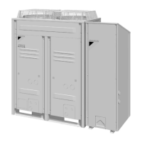
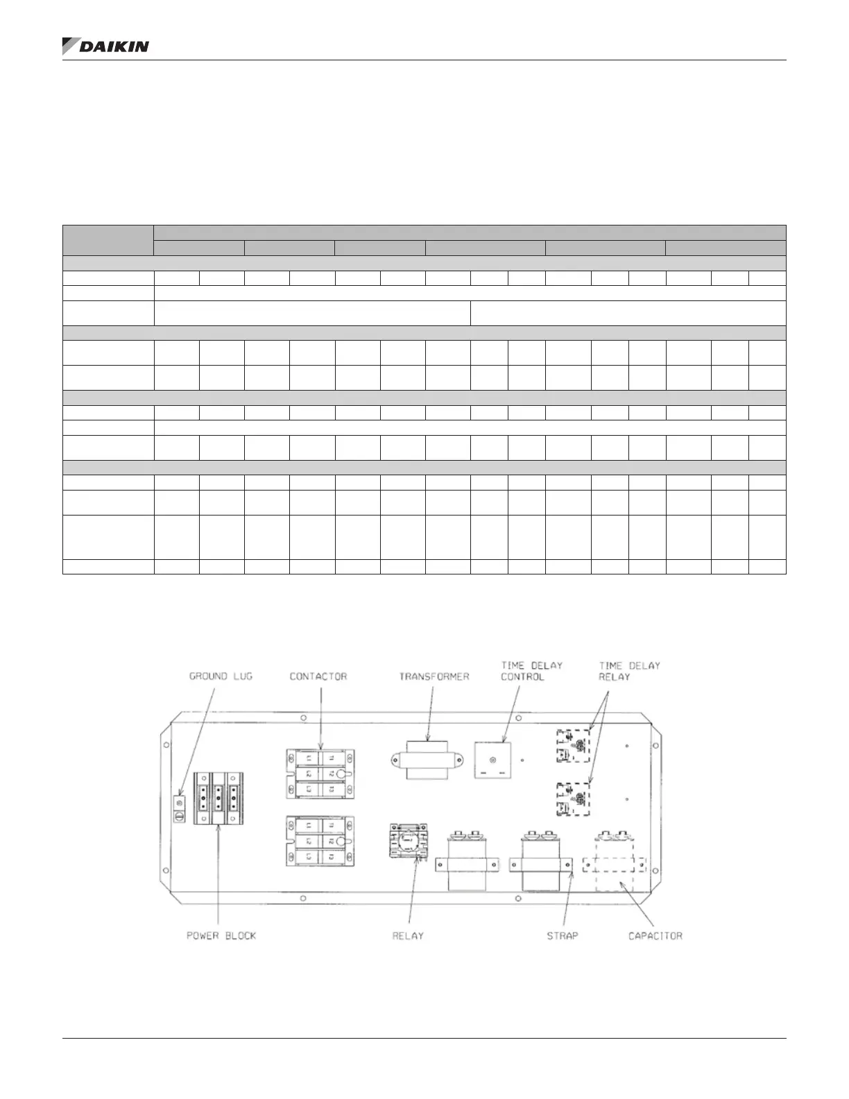
Figure 6: Control Box Example – RCS 10G Through 20F
www.DaikinApplied.com 9 IM 962-4 • AIR-COOLED SPLIT SYSTEM CONDENSERS
 Loading...