6
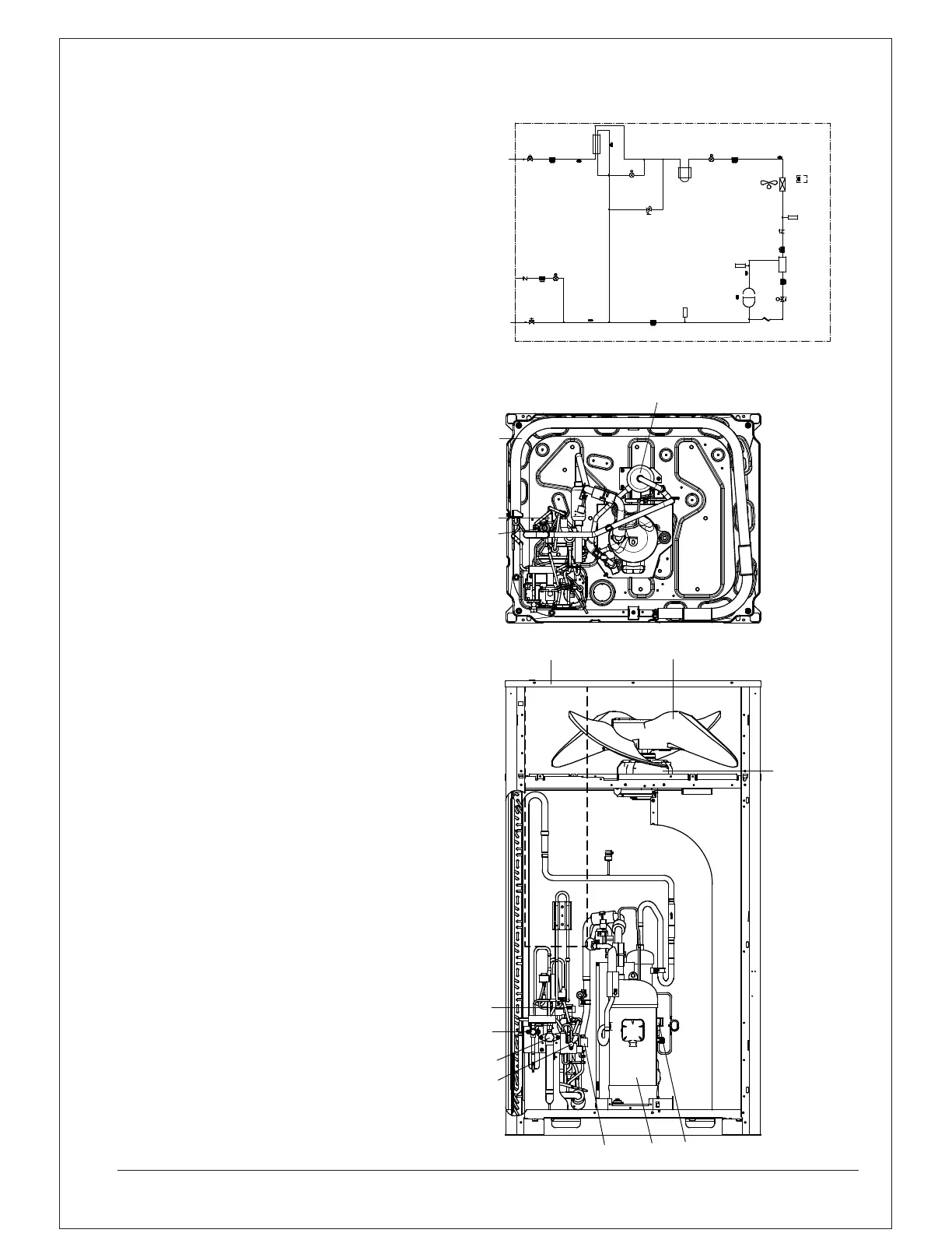
5.2.1 RXQ (6~12 HP)
Piping diagram
Outlook drawing
M
Liquid
pipe
Refrigerant
Auto charge
port
Gas
pipe
Double tube
Heat exchanger
Filter
R5T
R6T
Eletronic expansion
Valve
(Y2E)
Pressure
regulation
valve
Electronic Expansion
valve (main)
Heat sink PCB
(Y1E)
Filter
(S1NPL)
Low pressure
sensor
Electronic expansion
valve
(Y4E)
Filter
R3T
Filter
SENPL
(S1PH)
High pressure
switch
HPS
R21T
R8T
Compressor
INV
M1C
Capillary tube
Solenoid valve
(Y3S)
SV
Filter
Oil
Separator
Filter
Check valve
(S1NPH)
High pressure
sensor
SENPH
Heat exchanger
R1T
FAN
M1F
R4T
13
15
16
14
8
7
6
4
5
3
9
10
1
9
3
8
7
12
4
5
6
13
14
15
16
1
10
5.2 Main components in the unit
For all the models a piping diagram and outlook drawing are available.
Depending on the model type some components in the main
component list may not be existing in the unit.
Main components (see 5.2.1, 5.2.2, 5.2.3)
1 Compressor (M1C)
2 Compressor (M2C)
3 Heat exchanger
4 Fan
5 Fan motor (M1F, M2F)
6
7
Expansion valve, main (Y1E)
8
Expansion valve, subcool heat exchanger (Y2E)
9
10
Subcool heat exchanger
11
Oil separator
12
13
Solenoid valve, oil separator 1 (Y3S)
14
Solenoid valve, oil separator 2 (Y4S)
15
Electrical component box
16
Stop valve, liquid
Stop valve, gas
Stop valve, refrigerant auto charge
Expansion valve, refrigerant auto charge (Y4E)

 Loading...