30
HP
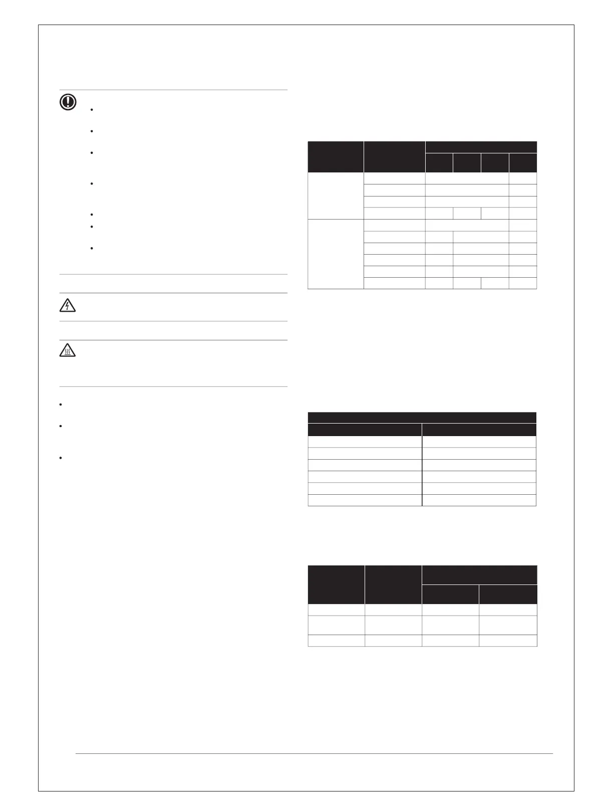
A parameter
(kg)
Total indoor unit
capacity CR
(a)
6~8 10~12 14~18 20
Piping
length≤30 m
50%≤CR≤105% 0 0.5
105%<CR≤130% 0.5
0.5
0.5
1.0
Piping
length>30 m
50%≤CR≤70% 0 0.5
70%<CR≤85% 0.3 0.5 1.0
1.0
85%<CR≤105% 0.7
0.7
1.0 1.5
105%<CR≤130%
130%<CR≤160%
160%<CR≤200%
130%<CR≤160%
160%<CR≤200%
1.2
1.2
1.2
1.5
1.5
1.7
1.5
1.3
2.0
2.0
2.3
2.5
14. Charging refrigerant
14.1 Precautions
To avoid compressor breakdown. Do not charge the refrigerant
more than the specified amount.
This outdoor unit is factory charged with refrigerant and
depending on pipe sizes and pipe lengths some systems require
additional charging of refrigerant.
In case re-charge is required, refer to the nameplate of the unit.
It states the type of refrigerant and necessary amount.
NOTICE
Refrigerant cannot be charged until field wiring has
been completed.
Refrigerant may only be charged after performing the
leak test and the vacuum drying.
When charging a system, care shall be taken that its
maximum permissible charge is never exceeded, in
view of the danger of liquid hammer.
Charging with an unsuitable substance may cause
explosions and accidents, so always ensure that the
appropriate refrigerant R410A is charged.
Refrigerant containers shall be opened slowly.
Always use protective gloves and protect your eyes
when charging refrigerant.
When the refrigerant system is to be opened,
refrigerant must be treated according to the applicable
legislation.
DANGER: Electrical shock
See
"2. General safety precautions".
14.2 Calculating the additional refrigerant charge
How to calculate the additional refrigerant to be charged
Additional refrigerant to be charged=R (kg). R should be rounded off
in units of 0.1 kg.
X
1...6
=Total length (m) of liquid piping size at Øa
When using metric piping, please take into account following table
concerning the weight factor to be allocated. It should be substituted
in the formula for R.
When selecting indoor unit, following table with connection ratio
limitation has to be respected. More detailed information can be
found in technical engineering data.
(a) CR=Connection ratio.
Piping length is considered the distance from the outdoor unit to
the farthest indoor unit.
Inch piping
Weight factor
Ø6.4 (1/4
”
)
Ø9.5 (3/8
”
)
Ø12.7 (1/2
”
)
Ø15.9 (5/8
”
)
Ø19.1 (3/4
”
)
Ø22.2 (7/8
”
)
Allowable capacity connection ratio
Used indoor
units
(a) Connection ratio.
VRV 50~200% 50~200% —
VRV +
RA
50~130% 0~130% 0~130%
RA 50~130% — 50~130%
RAVRVCR
(a)
Total
capacity
size (Ø) (mm)
0.022
0.057
0.11
0.17
0.26
0.36
R=[(X
1
@
Ø22.2) x 0.36+(X
2
@
Ø19.1) x 0.26+(X
3
@
Ø15.9) x 0.17+
(X
4
@
Ø12.7) x 0.11+(X
5
@
Ø9.5) x 0.057+(X
6
@
Ø6.4) x 0.022]+A
D
during power supply "ON" and after power supply
"OFF" suddenly.
ANGER: Do not touch electronic component box
See "2. General safety precautions".
In case of a multi-outdoor-unit system, add the sum of the individual
outdoor unit charge factors.

 Loading...