Connecting the power supply to multiple outdoor units
13. Making field settings
T
N
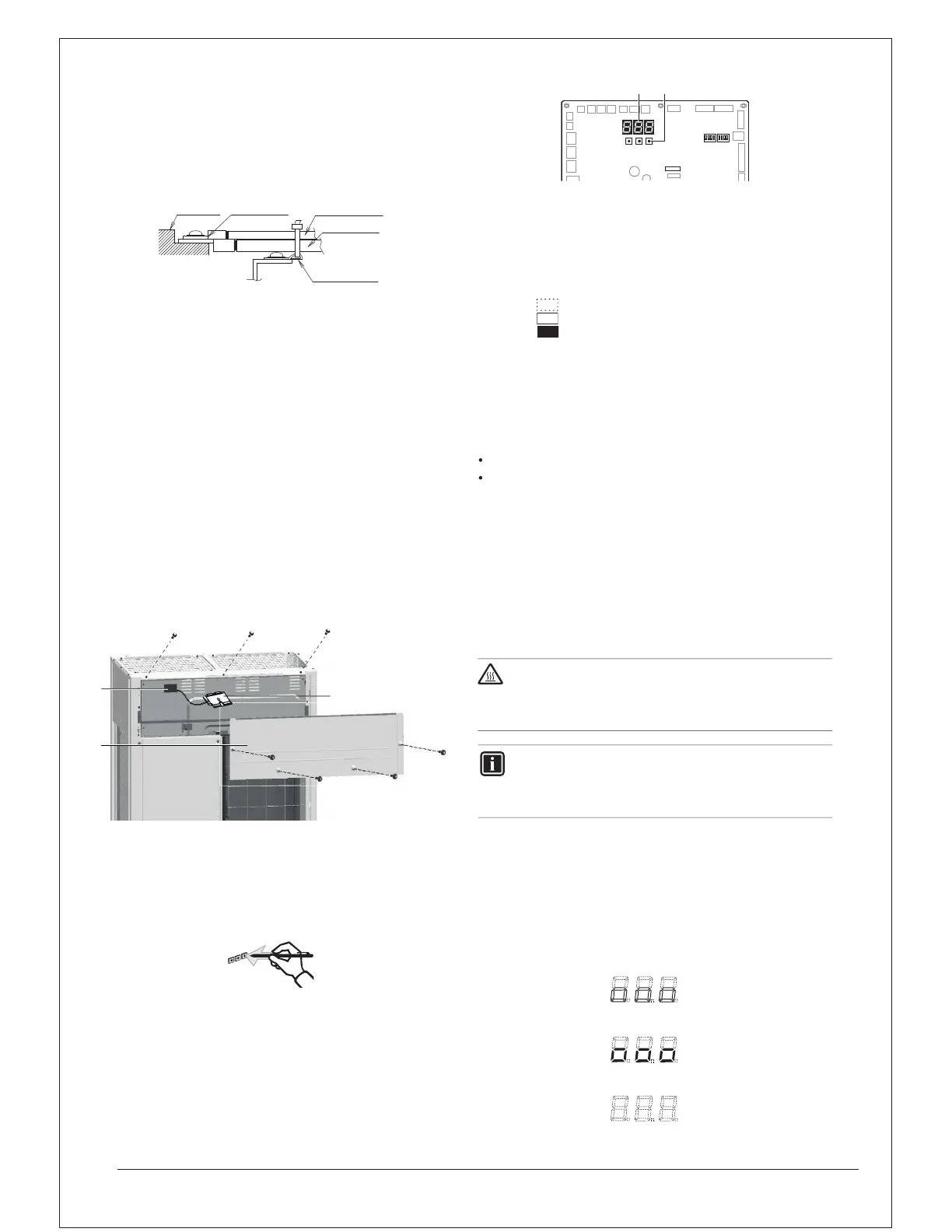
13.1 Accessing the push buttons on the logic board
T
N
BS1 MODE
BS2 SET
BS3 RETURN
DS1, DS2
1
2
N
13.2 Operating the push buttons and DIP switches on
the logic board
13.2.1 Operating the push buttons
T
Functions of the push button switches which are located on the
outdoor PCB (A1P)
N
N
INFORMATION
1 2
BS1 BS2
DS1 DS2
BS3
X27A
1
3
2
1
2
3
Terminal
block
Crip style
terminal
Wire: narrow
Wire: thick
Resin hook
D
during power supply "ON" and after power supply
"OFF" suddenly.
ANGER: Do not touch electronic component box

 Loading...