SiBE121021_C Check
Service Diagnosis 363
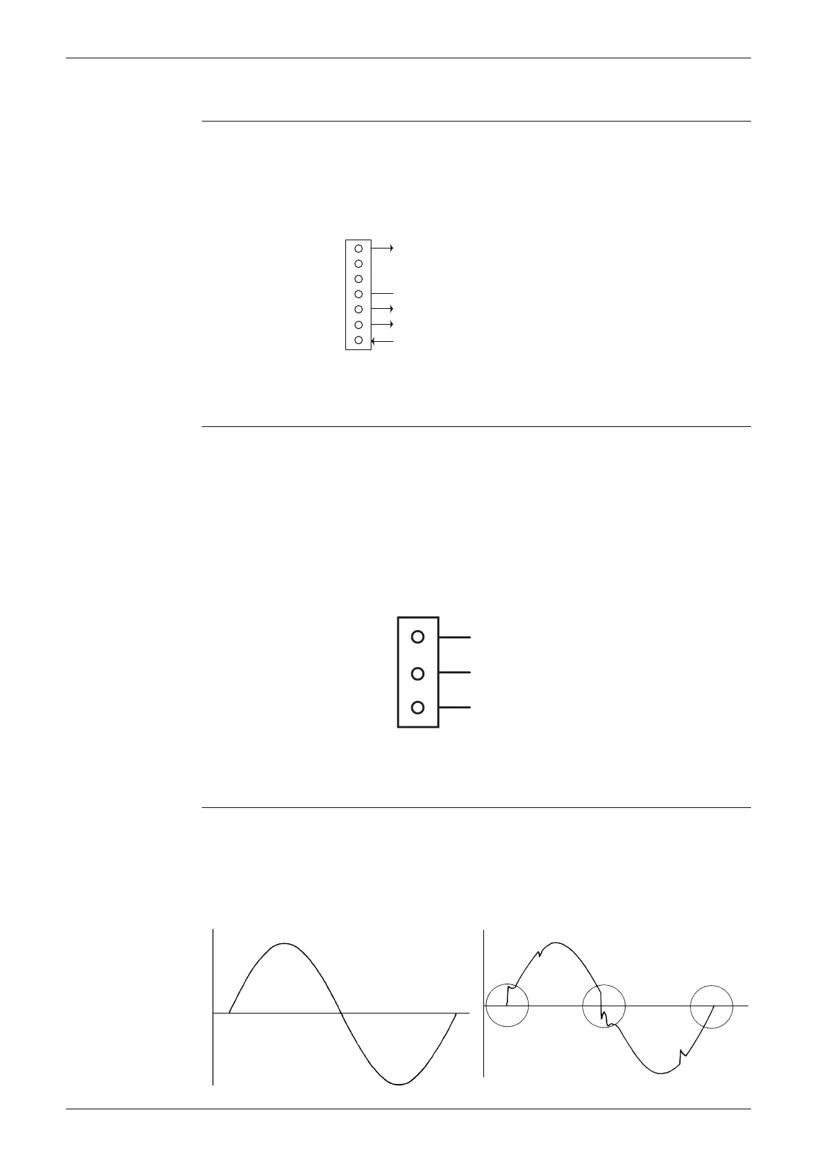
8.2 Fan Motor Connector Check
Check No.02 1. Check the connection of connector.
2. Check motor power supply voltage output (pins 4 - 7).
3. Check motor control voltage (pins 4 - 3).
4. Check rotation command voltage output (pins 4 - 2).
5. Check rotation pulse input (pins 4 - 1).
8.3 Hall IC Check
Check No.04 1. Check the connector connection.
2. With the power on, operation off, and the connector connected, check the following.
∗
Output voltage of about 5 V between pins 1 and 3.
∗
Generation of 3 pulses between pins 2 and 3 when the fan motor is operating.
If NG in step 1
Defective PCB
Replace the PCB.
If NG in step 2
Defective Hall IC
Replace the fan motor.
If OK in both steps 1 and 2
Replace the PCB.
8.4 Power Supply Waveform Check
Check No.11 Measure the power supply waveform between No. 1 and No. 2 on the terminal board, and check
the waveform disturbance.
Check to see if the power supply waveform is a sine wave (Fig.1).
Check to see if there is waveform disturbance near the zero cross (sections circled in Fig.2)
7
6
5
4
3
2
1
Motor power supply voltage (310 ~ 340 VDC)
Unused
Unused
GND
Motor control voltage (15 VDC)
Rotation command voltage (1~ 5 VDC)
Rotation pulse input
S1 or S200
(R14225)
1
Gray (power supply)
Purple (signals)
Blue (grounding)
2
3
(R14211)
S7
[Fig.1] [Fig.2]
(R1736)
(R1444)

 Loading...