10 Centrifugal Chillers IM 1044-2
Victaulic Couplings
Use the following steps when installing Victaulic couplings:
1. Check for smooth pipe between the pipe end and the groove. Remove any indentations, projections, or
weld seams. Failure to do this can result in a leaking joint.
2. Apply a thin coat of Victaulic or silicon lubricant to the gasket lips and exterior.
3. Position the gasket over the pipe end without overhanging the pipe.
4. Join the pipes together and slide the gasket into position, centering it between the groves.
5. Install the housing halves over the gasket, check that the housing’ keys engage the groves on both pipes.
6. Install the bolts and thread the nuts on hand tight. Make sure that the oval heads of the bolts seat properly
in the bolt holes.
7. Tighten the nuts evenly by alternating sides until metal to metal contact is made on the housing bolt pads
.
Mak
e sure that the housing keys completely engage the pipe grooves.
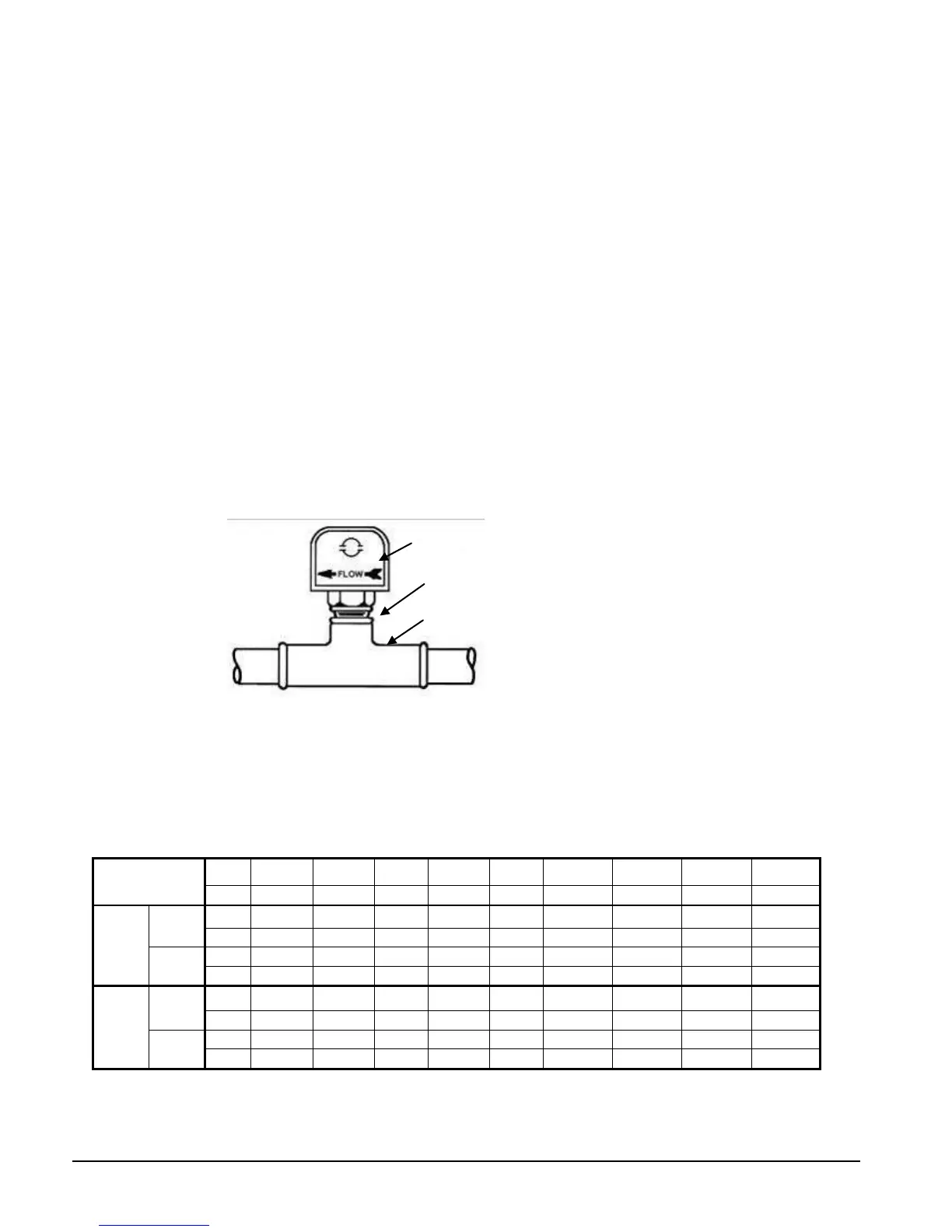
Flow Switch
A water flow switch must be installed in the vessel outlet piping to signal the presence of adequate water flow
to the vessels before the unit can start. They also serve to shut down the unit in the event that water flow is
interrupted to guard against evaporator freeze-up or excessive discharge pressure.
Thermal dispersion flow switches are available from Daikin as a factory-mounted option. It is
mounted in an evaporator and condenser water nozzle and factory wired.
A paddle type flow switch can be supplied by the owner for field mounting and wiring.
Figure 6, Flow Switch Mounting
I
f flow switches, by themselves, are used, electrical connections in the Unit Control Panel must be made from
the common T3-S terminal to terminal CF for the condenser switch and T3-S to terminal EF for the evaporator
switch. See Figure 19, Field Control Wiring Diagram on page 32. The normally open contacts of the flow
switch must be wired between the terminals. Flow switch contact quality must be suitable for 24 VAC, low
current (16ma). Flow switch wire must be in separate conduit from any high voltage conductors (115 VAC and
higher).
Table 1, Flow Switch Flow Rates
Pipe Size
(NOTE)
inch 1 1/4 1 1/2 2 2 1/2 3 4 5 6 8
mm 32 (2) 38 (2) 51 63 (3) 76 102 (4) 127 (4) 153 (4) 204 (5)
Min.
Adjst.
Flow
gpm 5.8 7.5 13.7 18.0 27.5 65.0 125.0 190.0 205.0
Lpm 1.3 1.7 3.1 4.1 6.2 14.8 28.4 43.2 46.6
No
Flow
gpm 3.7 5.0 9.5 12.5 19.0 50.0 101.0 158.0 170.0
Lpm 0.8 1.1 2.2 2.8 4.3 11.4 22.9 35.9 38.6
Max.
Adjst.
Flow
gpm 13.3 19.2 29.0 34.5 53.0 128.0 245.0 375.0 415.0
Lpm 3.0 4.4 6.6 7.8 12.0 29.1 55.6 85.2 94.3
No
Flow
gpm 12.5 18.0 27.0 32.0 50.0 122.0 235.0 360.0 400.0
Lpm 2.8 4.1 6.1 7.3 11.4 27.7 53.4 81.8 90.8
See notes next page.
Flow direction marked
on switch
switch connection

 Loading...


