40 Centrifugal Chillers IM 1044-2
Capacity Control System
The opening or closing of the inlet vanes controls the quantity of refrigerant entering the impeller thereby
controlling the compressor capacity. The vane movement occurs in response to oil flow from the SA or SB 4-way
solenoid valves, which in turn, respond to instructions from the unit microprocessor as it senses leaving chilled
water temperature. This oil flow activates a sliding piston that rotates the vanes.
Vane Operation
The hydraulic system for the inlet guide vane capacity control operation consists of a 4-way normally open
solenoid valve located in the oil management control panel or on the compressor close to the suction connection.
Oil under pressure from the oil filter is directed by the 4-way valve to either or both sides of the piston, depending
on whether the control signal is to load, unload, or hold.
To open the vanes (loading compressor), solenoid SA is de-energized and SB is energized, allowing oil flow from
port SA to one side of the piston. The other side drains through port SB.
To close the vanes (unload compressor), valve SB is de-energized and valve SA is energized to move the piston
and vanes toward the unload position.
When both solenoid valves SA and SB are de-energized, full oil pressure is directed to both sides of the piston
through ports SA and SB, and the vanes are held in that position. Refer to Figure 27 and Figure 28 for solenoid
action. Note that both solenoids cannot be energized simultaneously.
Vane Speed Metering Valves
The speed at which the capacity control vanes are opened or closed can be adjusted to suit system operating
requirements. Adjustable needle valves in the oil drain lines are used to control the rate of bleed-off and
consequently the “vane speed”. These needle valves are part of the 4-way solenoid valve assembly located in the
compressor lube box (Figure 26).
The valves are normally factory set so that the vanes will move from fully closed to fully opened in the time
periods shown in Table 14 on page 40.
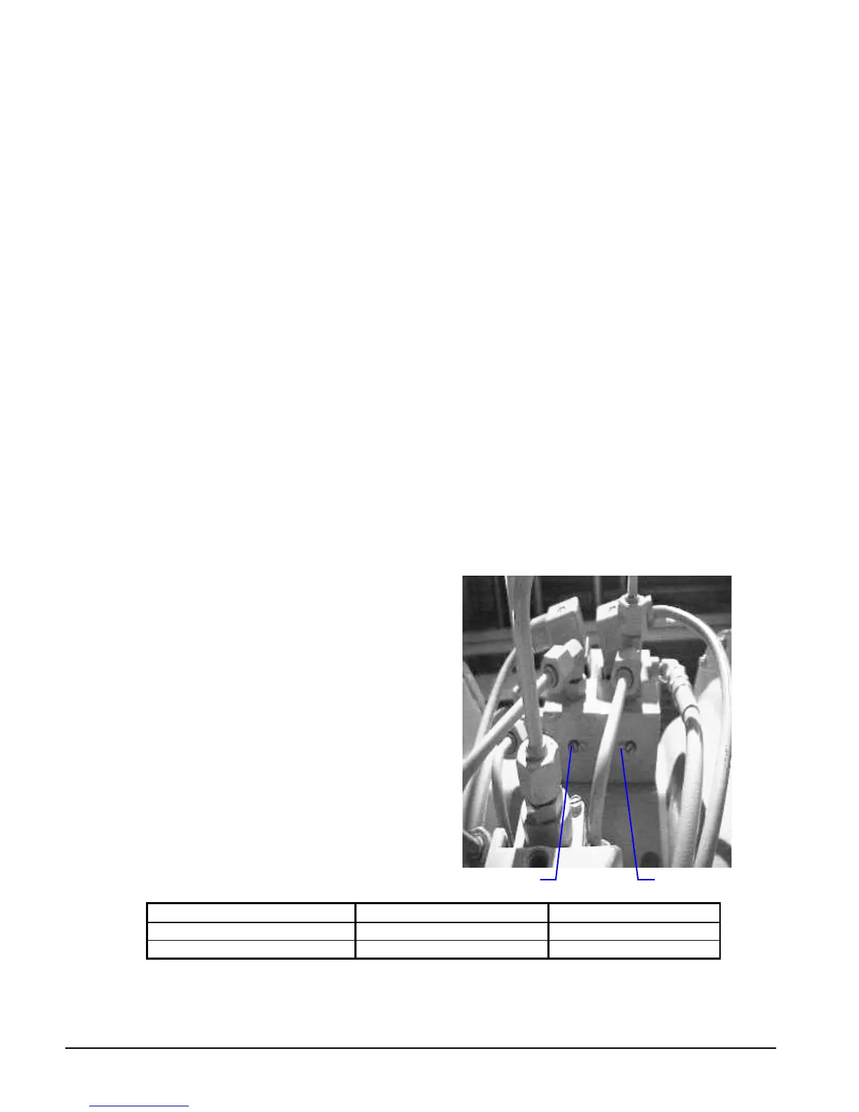
Figure 25, Needle Valve Location
The speed must be slow enough to prevent over-controlling
and hunting. The left adjusting screw is the SB needle
valve for adjusting the vane OPENING speed for loading
the compressor. Turn this screw clockwise to decrease the
vane opening speed and counterclockwise to increase the
opening speed.
The right adjusting screw is the SA needle valve for
adjusting the CLOSING speed to unload the compressor.
The same adjustment method applies; clockwise to
decrease closing, counterclockwise to increase vane
closing. These adjustments are sensitive. Turn the adjusting
screws a few degrees at a time. The vane speed is factory
set and varies by compressor size.
The start-up technician may readjust the vane speed at
initial start-up to meet job conditions.
Table 14, Vane Speed Factory Setting
Compressor Model Opening Time Closing Time
CE063 - CE100 3 - 5 min. 1 - 2 min
CE126 5 - 8 min. 1 - 2 min.
Figure 26, Oil Sump and Compressor Controller Panel
Close (Unload)

 Loading...


