6 Centrifugal Chillers IM 1044-2
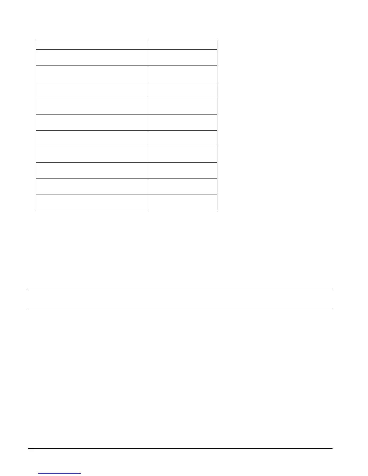
Operating/Standby Limits
Equipment room operating temperature:
Equipment room temperature, standby,
with water in vessels and oil cooler:
40°-104°F (4.4°-40°C)
Equipment room temperature, standby,
without water in vessels and oil cooler:
0°F-122F (-18°C-50°C)
Maximum entering condenser water
temperature, startup:
design + 5°F (2.7°C)
Maximum entering condenser water
temperature, operating:
temperature
Minimum entering condenser water
temperature, operating:
see following page.
Minimum leaving chilled water
temperature:
38°F (3.3°C)
Minimum leaving chilled fluid temperature
with correct anti-freeze fluid:
15°F (9.4°C)
Maximum entering chilled water
temperature, operating:
90°F (32.2°C)
Maximum oil cooler or VFD entering
temperature:
80°F (26.7°C)
Minimum oil cooler/VFD entering
temperature:
42°F (5.6°C)
Vibration Pads
The shipped-loose neoprene vibration pads should be located under the corners of the unit (unless the job
specifications state otherwise). They are installed to be flush with the sides and outside edge of the feet. Most
WSC units have six mounting feet although only the outer four are required. Six pads are shipped and the installer
can place pads under the middle feet if desired.
Mounting
Make sure that the floor or structural support is adequate to support the full operating weight of the complete unit.
It is not necessary to bolt the unit to the mounting slab or framework; but should this be desirable, 1 1/8" (28.5
mm) mounting holes are provided in the unit support at the four corners.
Note: Units are shipped with refrigerant and oil valves closed to isolate these fluids for shipment.
Valves must remain closed until start-up by the Daikin technician.
Nameplates
There are several identification nameplates on the chiller:
• The unit nameplate is located on the side of the Unit Control Panel. It has a Style No. XXXX and Serial N
o.
XX
XX. Both are unique to the unit and will identify it. These numbers should be used to identify the unit for
service, parts, or warranty questions. This plate also lists the unit refrigerant charge.
• Vessel nameplates are located on the evaporator and condenser. Along with other information, they have a
National Board Number (NB) and serial number, either of which identify the vessel (but not the entire unit).
• A compressor nameplate is located on the compressor itself and contains identification numbers.
System Water Volume
All chilled water systems need adequate time to recognize a load change, respond to that load change and
stabilize, without undesirable short cycling of the compressors or loss of control. In air conditioning systems, the
potential for short cycling usually exists when the building load falls below the minimum chiller plant capacity or
on close-coupled systems with very small water volumes.
Some of the things the designer should consider when looking at water volume are the minimum cooling load, the
minimum chiller plant capacity during the low load period and the desired cycle time for the compressors.

 Loading...


