38 Centrifugal Chillers IM 1044-2
Commissioning
This brief section on unit operation is included to assist in commissioning. Complete operating information is
contained in Daikin manual OM 1153.
During the initial startup of the chiller the Daikin technician will be available to answer any questions and instruct
in the proper operating procedures.
It
is recommended that the operator maintain an operating log for each individual chiller unit. In addition, a separate
maintenance log should be kept of the periodic maintenance and servicing activities.
This Daikin centrifugal chiller represents a substantial investment and deserves the attention and care
normally given to keep this equipment in good working order. If the operator encounters abnormal or unusual
operating conditions, it is recommended that a Daikin service technician be consulted.
Daikin conducts training for centrifugal operators at its factory Training Center in Staunton, Virginia, several times
a year. These sessions are structured to provide basic classroom instruction and include hands-on operating and
troubleshooting exercises. For further information, contact your Daikin
representative.
Standby Power
It is essential that any centrifugal chiller connected to standby power come to a complete stop before being restarted
on grid power. This is usually not an issue when running on grid power and experiencing a grid power failure since
the chiller’s control will shut down the chiller and disconnect it from the power source for the stop-to-start setpoint
time. It will have come to a complete stop before restarting.
Attempting to switch back and forth from regular grid line power and auxiliary power while the compressor is
running can result in extreme transient torque that will severely damage the compressor.
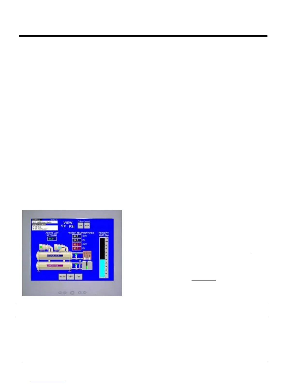
MicroTech II Control
Figure 22, MicroTech II Control Panel
All chillers are equipped with the Daikin
MicroTech II
control system consisting of:
• Opera
tor touchscreen interface panel (shown at the
left). It consists of a 15-inch Super VGA color screen and
a floppy drive. See Figure 22.
• Unit Control Panel containing the MicroTech II unit
controller and miscellaneous switches and field
connection terminals.
• Compressor Control Panel for each compressor
containing the MicroTech II compressor controller and
lube system control components.
NOTE: Detailed information on the operation of the MicroTech II control is contained in the OM
1153 available on
www.DaikinApplied.com.

 Loading...


