Instructions Unit installation
2.1 Installation of Air unit
and condensate line
Instructions for Air Units a
2
and a
3
– ceiling
units
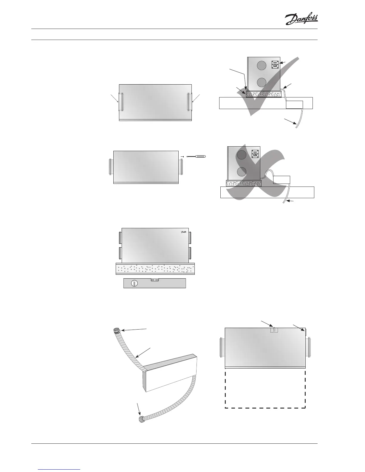
On delivery, the connectors will be inverted to
save space. Pull out the spigots.
Turn the spigots around and mount using the
tapping screws included. If a power drill is used,
the lowest torque setting should be used.
The unit should be placed on a platform, made
as a sandwich of 16 mm plywood or MDF sheet,
sandwiched around a 50 mm wall batts. It is very
important that the unit is mounted completely
horizontal. Use spirit level to check.
Check adjustment
Please note! A siphon must always be fitted
on the unit. The siphon is a Danfoss accessory
which must be ordered separately.
Hose clamp
3/4” re-inforced hose
3/4” threaded fitting
Siphon installation - correct
Joist
Siphon
To drain
If the unit is tilted, the function of the conden-
sate drain cannot be guaranteed, with risk of
water leakage as a result!
Mount the siphon on the rafter below the unit
or mount it in the room below the attic. If you
choose to mount your siphon in the attic, the
condensate duct must be made frost-proof.
Connect the pipe from the siphon to the conden-
sate spigot on the outlet. Lead the connected
pipe to the outlet, allowing for a gradient of min.
1 cm/metre.
Important: Remove front panel, and foam front
panel. Fill condensate tray, check the outlet and
reassemble.
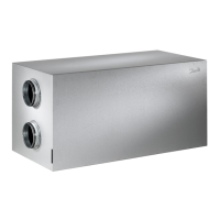
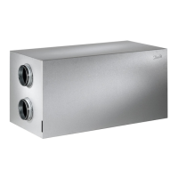
Attic units a
2
and a
3
top view
Service area
Condensate drain
Ø19 (smooth)
Supply air
Exhaust air
Outdoor air (intake)
Discharged air
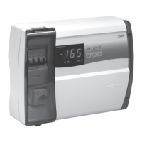
Power supply and
connection of CCM module
Important
Allow for 60 cm free space in front of unit, to
assure service access.
4
VIEWA402
 Loading...