AK-CC 550A Manual RS8FS402 © Danfoss 2016-03 11
Data communication
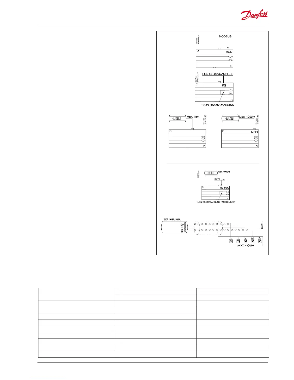
The controller has xed built-in MODBUS data communication.
If there is a requirement for a dierent form of data
communication, a Lon RS 485 or DANBUSS module can be
inserted in the controller.
The connection must then be to terminal RS 485.
(To use a Lon RS 485 module and gateway type AKA 245 the AKA
245 must be Version 6.20 or higher.)
Display
The controller has one plug for a display. Here display type EKA
163B or EKA 164B (max. length 15m) can be connected.
EKA 163B is a display for readings.
EKA 164B is both for readings and operation.
The connection between display and controller may be with a
cable which has a plug at both ends.
If the distance between display and controller is greater than 15
m, the connection must take another form.
An extra module must also be mounted in the controller if data
communication is used.
The built-in MODBUS data communication is used so that the
display connection and the data communication to the other
controllers must take place via a module. The module can be:
Lon RS 485, DANBUSS or MODBUS.
When a display is to be connected to the built-in MODBUS, the
display can advantageously be changed to one of the same type,
but with Index A (version with screw terminals).
The controllers address must be set higher than 0 in order for the
display to be able to communicate with the controller.
If connection of two displays is required, one must be connected
to the plug (max. 15 m) and the other must then be connected to
the xed data communication.
Important
All connections to the data communication MODBUS, DANBUSS
and RS 485 must comply with the requirements for data
communication cables. See literature: RC8AC.
Override
The controller contains a number of functions which can be used together with the override function in the master gateway/system
manager.
Function via data communication Function in gateway/system manager Used parameters in AK-CC 550A
Start of defrosting Defrost control / Time schedule / Defrost group --- Def start
Coordinated defrost Defrost control / Defrost group --- HoldAfterDef / - - - DefrostState
Prevent defrost start --- Disable Def
Day/Night schedule Day/Night control / Time schedule / Light zone --- Night setback
Light control Day/Night control / Time schedule O39 light Remote
Forced closing Forced Close / Injection ON / AKC ON --- Forced cl.
Forced cooling --- Forced cool
Railheat link to dew point / Enhanced railheat --- Dew point
P0 optimization P0 Optimization The controller supports P0 optimization
Adaptive defrost / Adaptive defrost. System manager only - - - Tc TempMean, MC Def.start
! Address
o03 > 0

 Loading...


