32 Manual RS8FS402 © Danfoss 2016-03 AK-CC 550A
DI1
Digital input signal.
The dened function is active when the input is short-circuited/
opened. The function is dened in o02.
DI2
Digital input signal.
The dened function is active when the input is short-circuited/
opened. The function is dened in o37.
Pressure transmitter
AKS 32R
Connect to terminal 30, 31 and 32.
(Used cable 060G1034: Black=30, Blue=31, Brown=32)
The signal from one pressure transmitter can be received by up
to 10 controllers. But only if there are no signicant pressure
decreases between the evaporators to be controlled. See
drawing on page 34.
S2, S6
Pt 1000 ohm sensor
S6 / S5B / S3B, product sensor or defrost sensor B or air sensor B.
The application determines which.
S3, S4, S5
Pt 1000 ohm sensor or PTC 1000 ohm sensor. All have to be of
the same type.
S3, air sensor, placed in the warm air before the evaporator
S4, air sensor, placed in the cold air after the evaporator
(the need for either S3 or S4 can be deselected in the
conguration)
S5, defrost sensor, placed on the evaporator
EKA Display
If there is be external reading/operation of the controller, display
type EKA 163B or EKA 164B can be connected.
RS485 (terminal 51, 52, 53)
For data communication, but only if a data communication
module is inserted in the controller. The module can be a LON
RS485, DANBUSS or a MODBUS.
Terminal 51 = screen
Terminal 52 = A (A+)
Terminal 53 = B (B-)
(For LON RS485 and gateway type AKA 245 the gateway must be
version 6.20 or higher.)
RJ45
For data communication, but only if a TCP/IP module is inserted in
the controller. (OEM specic)
MODBUS
For data communication.
Terminal 56 = screen
Terminal 57 = A+
Terminal 58 = B-
(Alternatively the terminals can be connected to an external
display type EKA 163A or 164A, but then they cannot be used
for data communication. Any data communication must then be
carried out by one of the other methods.)
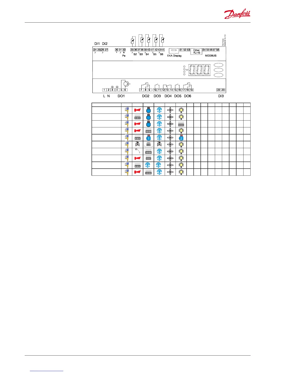
Supply voltage
230 V a.c.
Connections
Overview of outputs and
applications.
See also electrical diagrams earlier
in the manual
Application DO1 DO2 DO3 DO4 DO5 DO6 DI1 DI2 DI3 AI1 AI2 AI3 AI4 AI5 AI6
1
• • •
P0 S2 S3 S4 S5 S6
2
• • •
P0 S2 S3 S4 S5 S6
3
• • •
P0 S2 S3 S4 S5 S6
4
• • •
P0 S2 S3 S4 S5 S6
5
• • •
P0 S2 S3 S4 S5 S6
6
suction
hotgas
• • •
P0 S2 S3 S4 S5 S6
7
Blinds
• • •
P0 S2 S3 S4 S5 S6
8
heat
• • •
P0 S2 S3 S4 S5 S6
9
2 1
• • •
P0 S2 S3 S4 S5 S5B
10
• • •
P0 S2 S3 S4 S5 S3B

 Loading...


