AK-PC 772A Capacity controller RS8HF102 © Danfoss 2017-07 37
Determine the connection points
All connections must be programmed with module and point, so
in principle it does not matter where the connections are made, as
long as it takes place on a correct type of input or output.
• The controller is the first module, the next one is 2, etc.
• A point is the two or three terminals belonging to an input or
output (e.g. two terminals for a sensor and three terminals for a
relay).
The preparation of the connection diagram and the subsequent
programming (configuration) should take place at the present
time. It is most easily accomplished by filling in the connection
survey for the relevant modules.
Principle:
Name On module On Point Function
fx Compressor 1 x x Close
fx Compressor 2 x x Close
fx Alarm relay x x NC
fx Main switch x x Close
fx P0 x x AKS 32R 1-6 bar
The connection survey from the controller and any extension
modules are uploaded from the paragraph "Module survey. E.g.
controller module:
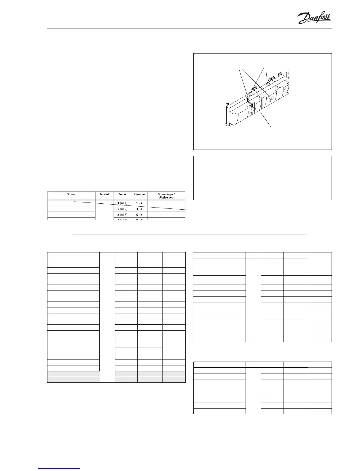
Module Point
10
Mind the numbering.
The right-hand part of the
controller module may look like
a separate module. But it isn’t.
- Columns 1, 2, 3 and 5 are used for the programming.
- Columns 2 and 4 are used for the connection diagram.
Signal Module Point
Terminal
Signal type /
Active at
1
1 (AI 1) 1 - 2
Shr Receiver temperature 2 (AI 2) 3 - 4 Pt 1000
3 (AI 3) 5 - 6
Suction gas temperature - Ss MT 4 (AI 4) 7 - 8 Pt 1000
Discharge temperature - Sd MT 5 (AI 5) 9 - 10 Pt 1000
Suction pressure - P0 MT 6 (AI 6) 11 - 12 AKS 2050-59
Condensing pressure - Pc MT 7 (AI 7) 13 - 14 AKS 2050-159
8 (AI 8) 19 - 20
Suction gas temperature - Ss LT 9 (AI 9) 21 - 22 Pt 1000
Discharge temperature - Sd LT 10 (AI 10) 23 - 24 Pt 1000
Suction pressure - P0 LT 11 (AI 11) 25 - 26 AKS 2050-59
Compressor 1 MT 12 (DO 1) 31 - 32 ON
Compressor 2 MT 13 (DO 2) 33 - 34 ON
Compressor 3 MT 14 (DO 3) 35 - 36 ON
Compressor 1 LT 15 (DO 4) 37 - 38 ON
Compressor 2 LT 16 (DO 5) 39 - 40 - 41 ON
Valve and circulation pump HR 17 (DO6) 42 - 43 - 44 ON
Fan motors 18 (DO7) 45 - 46 - 47 ON
Hot gas dump 19 (DO8) 48 - 49 - 50 ON
24 -
25 -
Example continued
Note
The safety relays should not be fitted onto a module
with override changeovers, as they can be put out of
operation by an incorrect setting.
Signal Module Point/Step Terminal Signal type
Compressor 1 MT Gen. Safety
2
1 (AI 1) 1 - 2 Open
Compressor 2 MT Gen. Safety 2 (AI 2) 3 - 4 Open
Compressor 3 MT Gen. Safety 3 (AI 3) 5 - 6 Open
All compressors common safety
MT
4 (AI 4) 7 - 8 Open
Compressor 1 LT Gen. Safety 5 (AI 5) 9 - 10 Open
Compressor 2 LT Gen. Safety 6 (AI 6) 11 - 12 Open
All compressors common safety LT 7 (AI 7) 13 - 14 Open
8 (AI 8) 15 - 16
Stepper signal to by-pass valve,
CCM
9 (step 1)
25 - 26 - 27 - 28
CCM (ETS)
10 (step 2) 29 - 30 - 31 - 32
Stepper signal to high pressure
valve, CCMT
11 (step 3) 33 - 34 - 35 - 36 CCMT
12 (step 4) 37 - 38 - 39 - 40
Signal Module Point Terminal Signal type
Outdoor temperature Sc3
3
1 (AI 1) 1 - 2 Pt 1000
Temp. gas cooler outlet Sgc 2 (AI 2) 3 - 4 Pt 1000
Gas cooler pressure Pgc 3 (AI 3) 5 - 6 AKS 2050-159
Receiver pressure Prec 4 (AI 4) 7 - 8 AKS 2050-159
Speed control, compressor MT 5 (AO 1) 9 - 10 0 - 10 V
Speed control, compressor LT 6 (AO 2) 11 - 12 0 - 10 V
Speed control, compressor, EC 7 (AO 3) 13 - 14 0 - 10 V
8 (AO 4) 15 - 16
Continued next page

 Loading...


