5.2 Connection heat transfer fluid
5.2.1 System solution 1
In system solution 1 the heat pump can produce both heating and hot water with the compressor and the integra-
ted auxiliary heater. Production of heating and hot water cannot occur at the same time because the exchange
valve for heating/hot water is positioned after the auxiliary heater.
The integrated auxiliary heater carries out peak heating charging (antilegionella function) in those operating
modes that permit auxiliary heat.
For system solution 1, select the factory setting in menu SERVICE\AUX. HEATER\EXTERNAL ADDITION:
EXTERNAL AUX. HEATER = 0 (Off)
REV.V. HOT WATER = INT
5.2.1.1 Example system solution 1
System solution for DHP-H, DHP-H Opti, DHP-H Opti Pro, DHP-C, DHP-A, DHP-A Opti.
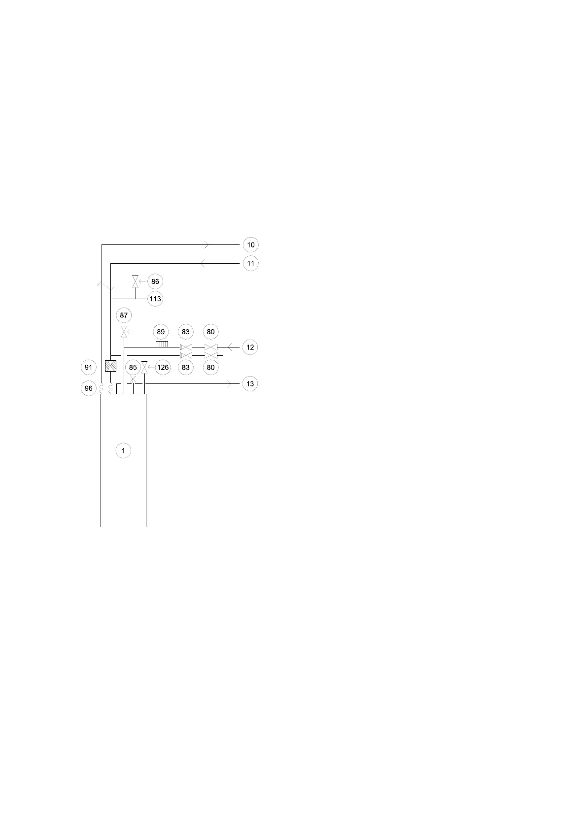
Figure 16. Example system solution 1
Symbol explanation
1 Heat pump
10 Supply line
11 Return line
12 Cold water
13 Hot-water
80 Shut-off valve
83 Non-return valve
85 Venting valve
86 Safety valve expansion heating system
87 Safety valve cold water 9 bar
89 Vacuum valve
91 Strainer
96 Flexible hose
113 Expansion heating system
126 Safety valve for temperature and pressure (only
applies to certain models)
Installation instructions VMBMA1002 – 23
 Loading...


